Antenna array fault diagnosis method based on sparse Bayesian learning

A sparse Bayesian, fault diagnosis technology, applied in antenna radiation patterns, measurement devices, instruments, etc., to solve problems such as less research on conformal array antenna fault diagnosis technology

Inactive Publication Date: 2017-08-04
UNIV OF ELECTRONICS SCI & TECH OF CHINA
View PDF5 Cites 17 Cited by
  • Summary
  • Abstract
  • Description
  • Claims
  • Application Information

AI Technical Summary

Problems solved by technology

[0004] At present, most of the existing array fault diagnosis algorithms are mainly applied to planar arrays such as planar arrays, linear arrays, and circular arrays, and there are few researches on fault diagnosis techniques for non-planar conformal array antennas.

Method used


Image

  • Antenna array fault diagnosis method based on sparse Bayesian learning
  • Antenna array fault diagnosis method based on sparse Bayesian learning
  • Antenna array fault diagnosis method based on sparse Bayesian learning

Examples


Embodiment Construction

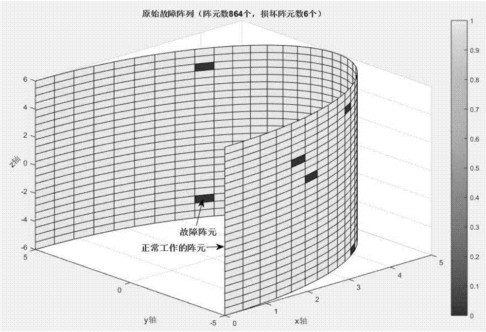
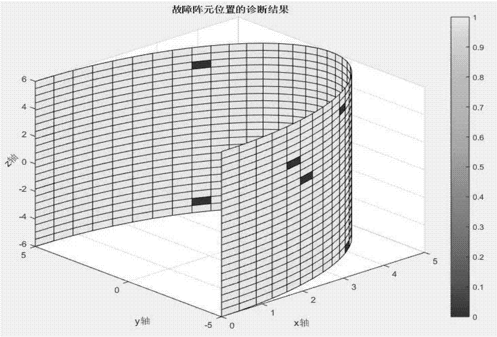
[0020] The faulty array considered in this embodiment is a cylindrical array with a radius of r=5λ and a height of 12λ, where λ is the wavelength. The array contains a total of 864 array elements, of which 36 array elements are arranged at equal intervals along the φ (azimuth angle) direction, and 24 array elements are arranged at equal intervals along the z-axis direction.

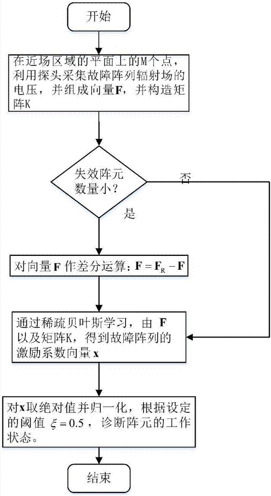
[0021] Step 1: In the near-field area, measure the voltage generated by the radiation field of the faulty array, and form the vector F from the measured voltage values.

[0022] In this embodiment, the voltage generated by the fault array radiation field is measured on a spherical surface with a radius of 7.5λ, an azimuth angle φ∈[-120°, 120°], and an elevation angle θ∈[-120°, 120°]. There are 600 measurement points on the sphere, and 30 and 20 field points are evenly arranged along the φ and θ directions, respectively.

[0023] Step 2: According to the formula Construct matrix K∈C M×N , where M=600 i...


PUM


Abstract

The invention discloses an antenna array fault diagnosis method based on sparse Bayesian learning, and relates to the field of antenna array signal processing. The method includes: measuring the voltage of a fault array by employing a probe at a plurality of measuring points of a near-field area; then performing sparse processing on a measured voltage data vector (performing difference operation on the measured voltage data vector and a near-field voltage data vector of a faultless array), and reconstructing an excitation vector of the fault array through a sparse Bayesian learning algorithm by employing the sparse data vector; and then calculating the quantity and the positions of array elements according to the excitation vector obtained by reconstruction to realize the goal of the method. Compared with the conventional array fault diagnosis algorithm, according to the method, the required near-field data samples are less, the success rate of diagnosis is higher, and the method can be applied to a conformal antenna array in any three-dimensional structure.

Description

technical field [0001] The invention relates to the field of antenna array signal processing, in particular to an antenna array fault diagnosis method. Background technique [0002] In recent years, array antennas have been widely used in military fields such as radars, sonar systems, and satellite communications because of their advantages such as good space radiation directivity. In practical engineering applications, large array antennas often consist of hundreds or even thousands of radiating array elements according to a specified spatial layout. However, as the scale of the array becomes larger, the probability of failure of array elements in the array increases. The failure of these elements will cause a sharp change in the field strength across the array aperture, thereby increasing the peak sidelobe level and fluctuation level of the pattern, and finally causing the array to fail to form a good beam pattern. When an array element fails, it can be solved by directl...

Claims


Application Information

Patent Timeline
Patent Type & Authority Applications(China)
IPC IPC(8): G01R29/10G01R19/00
CPCG01R19/0084G01R29/10
Inventor 龙政斌张瑛赵华鹏
Owner UNIV OF ELECTRONICS SCI & TECH OF CHINA
Why Eureka
Try Eureka