Battery pack monitoring system and monitoring method thereof

A technology for monitoring systems and battery packs, applied in battery circuit devices, safety/protection battery circuits, arrangement of multiple synchronous batteries, etc., can solve problems such as unreasonable module settings and unintuitive status information

Active Publication Date: 2017-08-04
BMTPOW LTD
View PDF3 Cites 17 Cited by
  • Summary
  • Abstract
  • Description
  • Claims
  • Application Information

AI Technical Summary

Problems solved by technology

[0003] Aiming at the problems of insufficient temperature state monitoring, unreasonable module setting, and unintuitive state information in the existing battery management system, the present invention provides a battery pack monitoring system and its method, reasonably setting integrated modules, and avoiding excessive temperature of the BMS main control unit. High;

Method used


Image

  • Battery pack monitoring system and monitoring method thereof

Examples


Embodiment approach

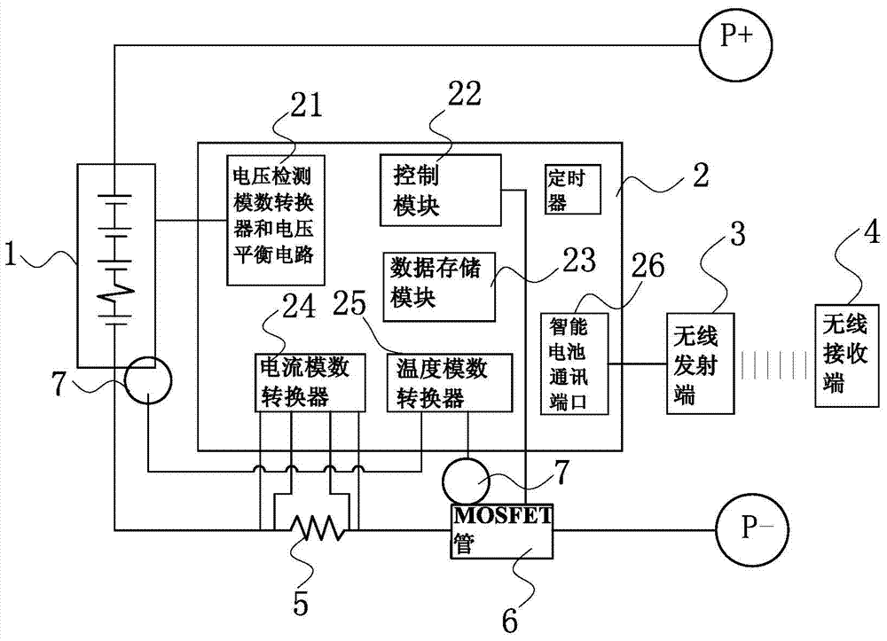
[0098] As a preferred embodiment of the present invention, the battery pack monitoring system further includes a plurality of LED lights for displaying power and battery status, and an LED control port is also integrated on the BMS main control unit, and the LED lights connected to the LED control port; the LED lights include a first LED light, a second LED light, a third LED light and a fourth LED light;

[0099] When charging:

[0100] The first LED light flashes: indicating that the power is less than 25%;

[0101] The second LED light flashes: indicating that the power is less than 50%;

[0102] The third LED light flashes: indicating that the power is less than 75%;

[0103] The fourth LED flashes: it means the power is greater than 75%;

[0104] All LED lights flashing: Indicates that the power detection system is faulty;

[0105] When not charging:

[0106] The second LED light flashes: it means the charger is faulty;

[0107] The third LED light flashes: it means...

Embodiment

[0115] Taking the 10S battery pack as an example, the battery pack monitoring system used in this embodiment is consistent with the above, and will not be described again. The monitoring method for the 10S battery pack includes the following steps:

[0116]Step 1: Parameter setting, input parameters into the BMS main control unit: overvoltage value 4250mV; overvoltage recovery value 4050mV; overvoltage protection delay 2s; overvoltage protection recovery time; undervoltage value 2800mV; undervoltage recovery value 3250mV ;Undervoltage protection delay 3s; Undervoltage protection recovery time; Charging high temperature protection value 45°C, charging high temperature protection recovery value 40°C, charging high temperature protection delay 2s, charging low temperature protection value 0°C, charging low temperature protection recovery value 3°C , charging low temperature protection delay 2s; discharge high temperature protection value 60°C, discharge high temperature protection...


PUM


Abstract

The invention provides a battery pack monitoring system. The battery pack monitoring system comprises battery package and a wireless receiving end, wherein the battery package comprises a battery pack, a battery management system (BMS) master control unit, a current detection resistor, a metal-oxide-semiconductor field effect transistor (MOSFET), a plurality of temperature detection probes and a wireless emission end, wherein the battery pack, the current detection resistor and the MOSFET are connected in series, the battery pack is formed by electrically connecting a plurality of single batteries and is provided with a positive connection end and a negative connection end, the plurality of temperature detection probes are respectively attached onto surfaces of the battery pack and the MOSFET, a control module, a data storage module and an analog-to-digital conversion module are integrated onto the BMS master control unit, the analog-to-digital conversion module is connected with the control module, the data storage module is connected with the control module, and the control module is connected with the MOSFET. Meanwhile, the invention also discloses a monitoring method of the battery pack monitoring system. The battery pack monitoring system aims to solve the problems of insufficient monitoring on a temperature state, unreasonable module setting and unintuitive state information of an existing BMS.

Description

technical field [0001] The invention relates to a battery pack monitoring system and a monitoring method thereof. Background technique [0002] At present, various electric transportation devices have been widely used in people's lives. Secondary batteries have the following disadvantages, such as less stored energy, short life, problems in series and parallel use, safety in use, and difficulty in estimating battery power. The performance of batteries is very complex, and the characteristics of different types of batteries vary greatly. Although the existing battery pack management system can detect the current and voltage status to a certain extent, it is insufficient to monitor the temperature of electronic components such as MOSFET tubes, or only detects the temperature of the battery pack, ignoring its impact on battery functions. The battery management system The module setting is unreasonable, and the MOSFET tube with high heat generation and the current detection res...

Claims


Application Information

Patent Timeline
IPC IPC(8): H02J7/00
CPCH02J7/0026Y02E60/10
Inventor 苏哲锋张志贤王大瑞刘宝忠罗仑
Owner BMTPOW LTD
Why Eureka
Try Eureka