Continuous flattening and paper-attaching production line for single plates

A production line and paper-covering technology, which is applied in the field of veneer continuous smoothing and paper-covering production line, can solve the problems of bulging equipment structure, uneven lamination, complex operation, etc., and achieve high quality, good effect and simple structure Effect

Active Publication Date: 2017-08-08
贵港市东海木业有限公司
View PDF6 Cites 5 Cited by
  • Summary
  • Abstract
  • Description
  • Claims
  • Application Information

AI Technical Summary

Problems solved by technology

[0006] The purpose of the present invention is to address the deficiencies of the prior art, by placing the paper and the board in the upper and lower positions and then pushing the facial paper to the middle to fit the board, and then spre

Method used


Image

  • Continuous flattening and paper-attaching production line for single plates
  • Continuous flattening and paper-attaching production line for single plates
  • Continuous flattening and paper-attaching production line for single plates

Examples


Embodiment 1

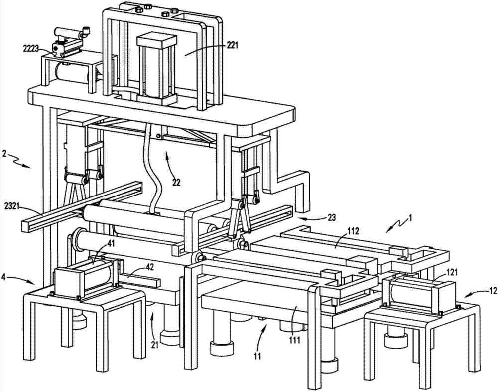
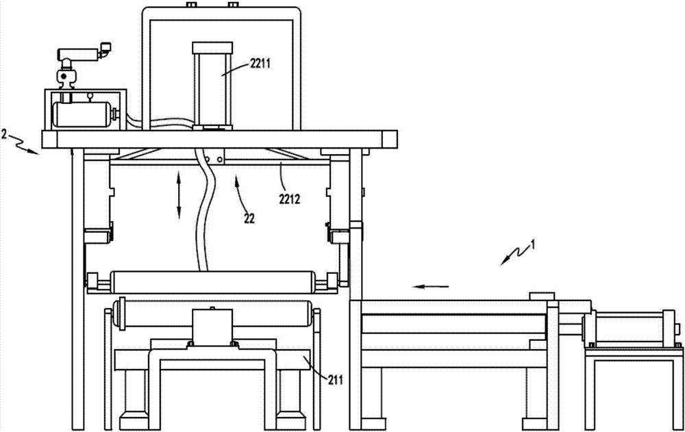
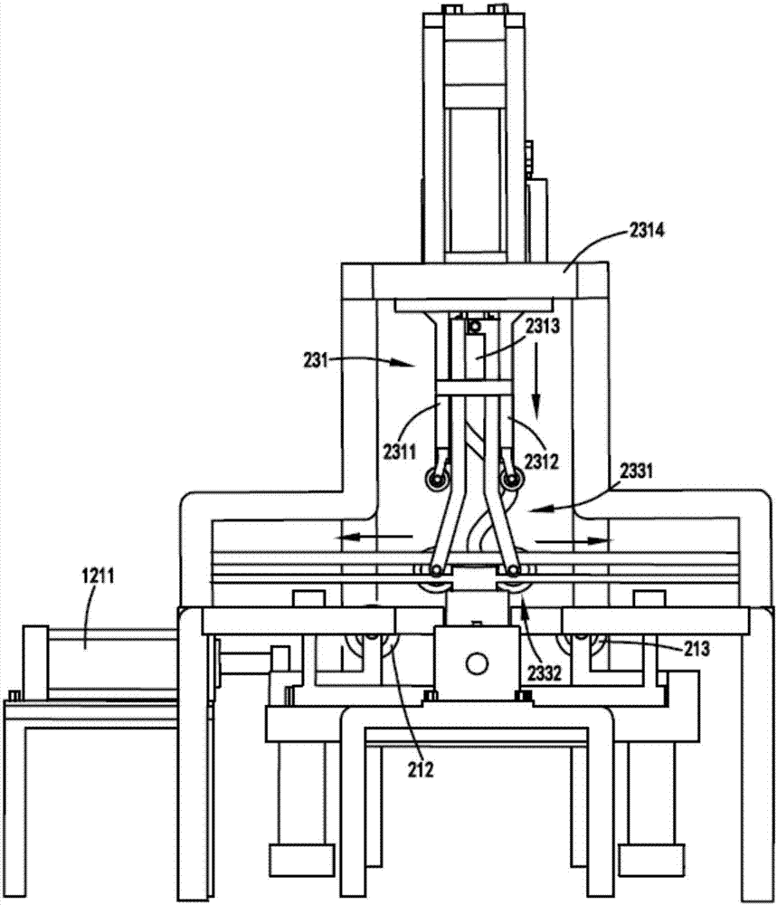
[0041] figure 1 It is a schematic diagram of the structure of the automatic pasting equipment, figure 2 It is a schematic diagram of the front view of the automatic pasting equipment, image 3 It is a schematic diagram of the side view of the automatic pasting equipment, Figure 4 It is a schematic diagram of the structure of the bonding part, Figure 5 It is a schematic diagram of the structure of the adsorption fixing device and the bonding device, Figure 6 It is a schematic diagram of when the surface paper and the sheet start to contact, Figure 7 Schematic diagram of the structure of the feeding part, Figure 8 It is a schematic diagram of the structure of the feeding mechanism, Figure 9 It is a schematic diagram of the structure of the bonding device. Such as figure 1 , figure 2 , image 3 , Figure 4 , Figure 5 , Figure 6 , Figure 7 , Figure 8 and Figure 9 As shown, a veneer continuous flattening paper production line includes a feeding part 1, a...

Embodiment 2

[0057] Such as figure 1 , figure 2 , image 3 , Figure 4 , Figure 5 , Figure 6 , Figure 7 and Figure 8 As shown, the components that are the same as or corresponding to those in the first embodiment are marked with the corresponding reference numerals in the first embodiment. For the sake of simplicity, only the differences from the first embodiment will be described below. The difference between the second embodiment and the first embodiment is that: the upper ends of the limiting plate a2311 and the limiting plate b2312 are provided with a sliding guide device 3, and the sliding guide device 3 includes a mounting frame 31 and a rotatable setting Guide pulley 32 on mounting frame 31.

[0058] The setting of the sliding guide device 3 can make the smoothing roller a2337 and the smoothing roller b2338 unfold to both sides or can be more smoothly recovered in the limiting channel 2313 on the one hand, and on the other hand, the smoothing roller a2337 and the smoothi...


PUM


Abstract

The invention relates to a continuous flattening and paper-attaching production line for single plates, which comprises a feeding part and an attaching part; the feeding part comprises a bearing mechanism and a feeding mechanism used for pushing a piece of surface paper and a plate with glue applied on the surface on the bearing mechanism to move together to an attaching station; and the attaching part comprises a supporting mechanism used for bearing the plate and the surface paper conveyed by the feeding mechanism, a pushing mechanism arranged upon the supporting mechanism and used for driving the surface paper to move in a direction toward the plate below, and attaching mechanisms arranged on both ends of the pushing mechanism and used for spreading the surface paper from the middle of the surface paper to both sides and attaching the surface paper to the plate. The invention overcomes the problems of uneven attaching and easy blistering existing in the method of attaching from one side to the other side and the problem of complex structure and unstable operation existing in conventional equipment.

Description

technical field [0001] The invention relates to the technical field of facial paper equipment, in particular to a continuous veneer smoothing and covering paper production line. Background technique [0002] In order to prevent scratches or bruises during subsequent transportation, some sheets are often pasted with a layer of protective paper on their surface after processing. [0003] A Chinese utility model patent with the authorized announcement number CN202037959U, which discloses a film and face paper device on the sheet material uncoiling, leveling, and shearing production line, which accurately feeds the sheet material, film tape or paper into the prescribed The position then utilizes the film roller to apply the film, but the equipment has the following problems: [0004] 1. The equipment structure is relatively complex, the cost is high, various positioning instruments are required, and the stability is poor. [0005] 2. During the lamination process, it cannot be...

Claims


Application Information

Patent Timeline
IPC IPC(8): B32B37/12B32B37/10B32B39/00
CPCB32B37/10B32B37/12B32B39/00
Inventor 陈高春
Owner 贵港市东海木业有限公司
Why Eureka
Try Eureka