
Modern intelligent pumping unit

A kind of pumping unit, intelligent technology, applied in the field of modern intelligent pumping unit, can solve the problems of increasing wearing parts, complicated process, unusable transmission structure, etc., to achieve the effect of reducing the amplitude

Inactive Publication Date: 2017-08-08
付尤东 +1
View PDF9 Cites 1 Cited by
  • Summary
  • Abstract
  • Description
  • Claims
  • Application Information

AI Technical Summary

Problems solved by technology

[0002] At present, the oil exploitation industry has more and more recognized the advantages of low energy consumption and high efficiency of the tower type combined transmission pumping unit. The combined transmission pumping unit disclosed by the publication number CN 101413387 B now used has simple structure, stable operation and low noise. It is small and has a good market prospect, but due to the limitations of the transmission structure, it cannot be used on medium and heavy-duty pumping units, and the life of the wire rope is short; the gears need to be adjusted; the combined transmission mechanism is all on one side of the tower, and the operating platform will generate a large amplitude and lateral force, the numerically controlled pumping units disclosed by publication numbers CN101555782 and CN101881145 are all devoting themselves to solving the problem of running balance and symmetry, but they cannot be implemented because of complex process, high cost and increased wearing parts; publication number CN 10775969 B The disclosed combined drive pumping unit without guide wheels solves the problem of the life of the wire rope, but with the addition of chain wearing parts, the workover clearance cannot meet the clearance distance requirements of all oil wells, especially the medium and heavy load pumping units are expensive , is not conducive to the application of the market; it is necessary to fill the gap in the market with intelligent pumping units with Internet + big data automatic control, so it is necessary to develop a new type of pumping unit to meet the needs of the market

Method used


Image

  • Modern intelligent pumping unit
  • Modern intelligent pumping unit
  • Modern intelligent pumping unit

Examples


Embodiment Construction

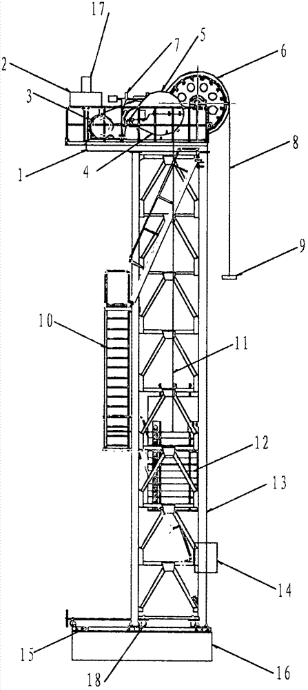
[0020] Such as figure 1 , figure 2 , Figure 4 , Figure 5 and Figure 6 As shown, the first embodiment of the modern intelligent pumping unit of the present invention includes that it is installed on the operating platform 1 at the top of the tower 13: a control system 2, a reminder light 17, a power system 3, a drum type electromagnetic power-off brake 7, First-level belt transmission 4, second-level gear transmission 5, third-level gear transmission 6, touch screen 14, balance counterweight system 12, drive rope 8, rope hanger 9, counterweight traction rope 11, workover mechanism 18, mobile The mechanism base 15, the control system 2 is a servo control system including an intelligent module and a touch screen, the control system 2 controls the reversing position and speed of the power system 3, and the primary small pulley 19 at the output end of the power system 3 is installed on the first transmission shaft 22 A belt 20 is set on the first-stage large pulley 21 at th...


PUM


Abstract

The invention discloses a modern intelligent pumping unit, relates to oil exploitation equipment and aims to provide a reducer-free series combined transmission pumping unit which uses the Internet+ without sensors, provides big data provided during driving of a servo controller and automatically regulates, controls and diagnoses the downhole liquid level and operation parameters through an expert analysis system. The modern intelligent pumping unit comprises an integrated driving system composed of a tower, a control system, a power system, a transmission system, a balance weight system, a counter weight pulling rope, a rope sheave, a driving rope, a beam hanger and a well repair yielding mechanism, a steel wire rope wound and fixed to the rope sheave is driven to move up and down, and thus oil exploitation operation is completed. Through the modern intelligent pumping unit, the problems of uneven stress of a whole unit and high amplitude due to the fact that a transmission system of an electronic control reversing pumping unit is centralized on one side of a platform are solved, the problems of high fault rate of reducers, high maintaining cost and cost and low stability are solved, the application range is enlarged, and the purpose that all types do not need to be overhauled is achieved; and the well repair yielding mechanism is safe and convenient to use.

Description

technical field [0001] The invention relates to a mechanical equipment for oil exploitation, in particular to a modern intelligent pumping unit. Background technique [0002] At present, the oil exploitation industry has more and more recognized the advantages of low energy consumption and high efficiency of the tower type combined transmission pumping unit. The combined transmission pumping unit disclosed by the publication number CN 101413387 B now used has simple structure, stable operation and low noise. It is small and has a good market prospect, but due to the limitations of the transmission structure, it cannot be used on medium and heavy-duty pumping units, and the life of the wire rope is short; the gears need to be adjusted; the combined transmission mechanism is all on one side of the tower, and the operating platform will generate a large amplitude and lateral force, the numerically controlled pumping units disclosed by publication numbers CN101555782 and CN10188...

Claims


Application Information

Patent Timeline
IPC IPC(8): E21B43/00F16H37/12
CPCE21B43/00F16H37/12
Inventor 付尤东毛宏伟张劲予关力
Owner 付尤东
Learn More