

Gas expansion device and machining method and application of neckings of expansion pipe
A technology of a gas expansion device and a processing method, which is applied in the directions of earth-moving drilling, discharging machinery, etc., can solve the problems of flying heads, high defective rate, heavy weight, etc., and achieves reduced production cost, small bearing surface, and simple structure. Effect
- Summary
- Abstract
- Description
- Claims
- Application Information
AI Technical Summary
Problems solved by technology
Method used
Image

Examples
Embodiment 1
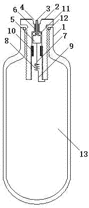
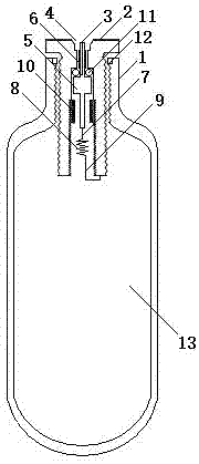
[0055]An expansion device, comprising an expansion tube 1 and an inflatable ignition head 2, one end of the expansion tube 1 is shrunk and sealed, and the other end is shrunk with an inflatable ignition head 2, and a storage tank is formed between the necked sealing end 104 and the inflatable ignition head 2 Energy chamber 13; the inflatable ignition head 2 includes an inflatable seat body 201, a through hole 202, a valve chamber 203, an ignition chamber 204, an inflatable nozzle 4, a conductive valve 5, an insulating layer 6, a heating wire 8, a retaining ring 10 and a first Sealing ring 11, inflatable seat body 201 upper end middle position is provided with inflatable mouth 4, is provided with through hole 202 under inflatable mouth 4, is provided with valve chamber 203 below through hole 202, is provided with ignition chamber 204 below valve chamber 203, valve chamber 203 is provided with a conductive valve 5 and a first sealing ring 11, and a retaining ring 10 is provided i...
Embodiment 2
[0059] As the expansion device described in Embodiment 1, in order to facilitate the connection of the heating wire 8, one end of the conductive valve 5 is an inflatable conductive thimble 501, the other end is a conductive needle 503, and when the middle part is a conductive valve core 502, the conductive needle 503 is connected to the heating wire 8 One end, the other end of the heating wire 8 is connected to the inflatable seat body 201; the expansion tube is made of non-ferrous metal material or metal alloy or ABS or steel or copper alloy or aluminum alloy; The energy pressure is directly proportional; the material strength of the conduction valve 5 is slightly greater than the energy storage pressure in the energy storage chamber 13 bottles.
Embodiment 3
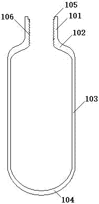
[0061] As the expansion device described in Embodiment 1 or 2, the bottle mouth 101 is provided with a sealing groove 105, and the sealing groove 105 is provided with a second sealing ring 12; The outer wall is provided with an external thread 206 matched with the internal thread 205; the thickness of the neck 102 is 20 mm, the thickness of the necked sealing end 104 is 20 mm, and the thickness of the bottle body 103 is 2 mm; the neck 102 of the expansion tube 1 and The shrinking sealing end 104 is formed by shrinking and thickening; the second sealing ring 12 is an O-ring.
PUM
| Property | Measurement | Unit |
|---|---|---|
| Thickness | aaaaa | aaaaa |
| Thickness | aaaaa | aaaaa |
| Thickness | aaaaa | aaaaa |
Abstract
Description
Claims
Application Information