Coupling structure of optical fiber array and PD array

A technology of fiber array and coupling structure, applied in the field of coupling structure, can solve the problems of incompetence of discrete methods, etc.

Inactive Publication Date: 2017-08-11
SHANGHAI BRANCH FUZHOU GAOYI COMM CO LTD
View PDF6 Cites 3 Cited by
  • Summary
  • Abstract
  • Description
  • Claims
  • Application Information

AI Technical Summary

Problems solved by technology

In the high-speed information transceiver system, it is necessary to replace the traditional optical modules with high-density optical modules and adopt multi-channel optical transceiver technology. In these modules, a very important function is to realize the reception and conversion of light beams. However, multiple The existence of discrete components makes the assembly error allowed when the optical module is packaged smaller, the alignment accuracy is higher, and the high optical coupling efficiency in the package is put forward higher requirements, and the module integration and miniaturization requirements are higher. In the high background, the discrete method seems powerless

Method used


Image

  • Coupling structure of optical fiber array and PD array
  • Coupling structure of optical fiber array and PD array
  • Coupling structure of optical fiber array and PD array

Examples


Embodiment Construction

[0015] The present invention will be described in detail below in conjunction with the accompanying drawings and specific embodiments.

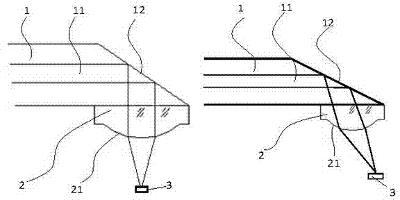
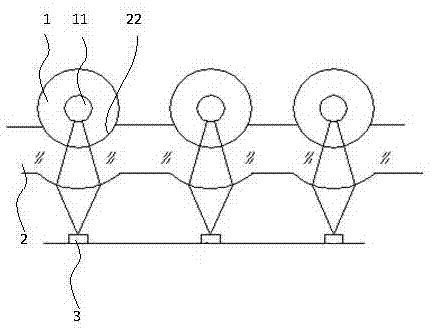
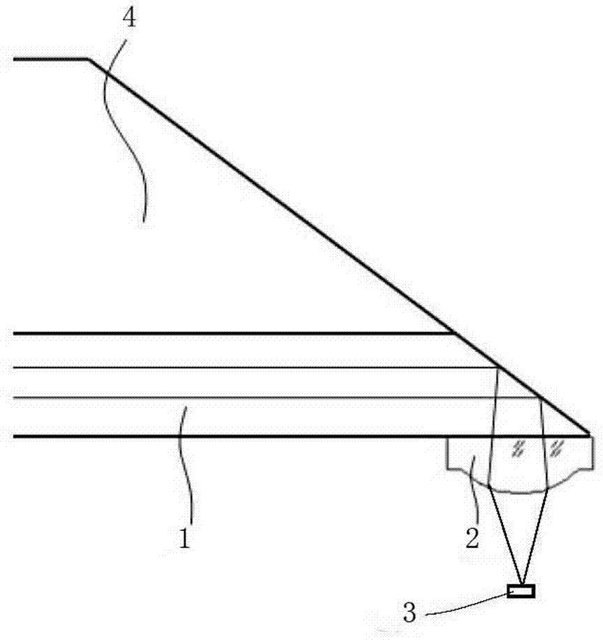
[0016] Depend on figure 1 and 2 As shown, a coupling structure between an optical fiber array and a PD array includes an optical fiber array 1 , a lens array 2 and a PD array 3 .

[0017] Optical fiber array 1, including several optical fibers, can be 1×4, 1×8, 1×12 core optical fibers or more, which are fixed in equal-spaced V-shaped grooves set on the glass block 4, and the end faces of the optical fiber array 12 It is ground into a certain angle with the vertical direction, depending on the material refractive index of the optical fiber used, and the total reflection angle calculated accordingly. The end face angle can be less than, equal to or greater than the total reflection angle. When it is smaller than the total reflection angle, A layer of high reflection film needs to be coated on the end surface to realize the total internal ref...


PUM


Abstract

The invention provides a coupling structure of an optical fiber array and a PD array. The coupling structure comprises the optical fiber array, a lens array and the PD array. The end surface of the optical fiber array is ground into a certain angle with the vertical direction. The angle is determined according to the total reflection angle calculated by the refractive index of the used optical fiber material and can be less than, equal to or greater than the total reflection angle. When the angle is less than the total reflection angle, a high reflection film requires to be coated on the end surface so as to realize total internal reflection of the light in the optical fibers. The light is emergent out of the cladding of the optical fibers and then enters the lens array. The adhesive surface of the lens array and the optical fiber array is manufactured to be matched with the shape of the optical fibers so as to facilitate high-accuracy assembling and positioning and reduce beam insertion loss. Besides, the external end curve of the lens array is manufactured to be aspheric so as to obtain higher coupling efficiency. Then the light enters the PD array so as to realize beam receiving and conversion. The coupling structure of the optical fiber array and the PD array has the advantages of high coupling efficiency, low insertion loss, small volume and simple assembling and debugging.

Description

technical field [0001] The invention relates to the technical field of optical fiber communication, in particular to a coupling structure for an optical fiber array and a PD array. Background technique [0002] With the increasing development of the communication field, traditional transmission technology has been difficult to meet the requirements of transmission capacity and speed. In typical application fields such as data centers, network connections, search engines, high-performance computing and other fields, high-speed transceiver modules meet High-density and high-speed data transmission requirements arise at the historic moment. In the high-speed information transceiver system, it is necessary to replace the traditional optical modules with high-density optical modules and adopt multi-channel optical transceiver technology. In these modules, a very important function is to realize the reception and conversion of light beams. However, multiple The existence of discr...

Claims


Application Information

Patent Timeline
Patent Type & Authority Applications(China)
IPC IPC(8): G02B6/42
CPCG02B6/4204G02B6/4214
Inventor 吴砺徐云兵刘洪彬王向飞林磊
Owner SHANGHAI BRANCH FUZHOU GAOYI COMM CO LTD
Why Eureka
Try Eureka