
Method for machining pipe based on laser cutting

A laser cutting and cutting process technology, applied in laser welding equipment, metal processing equipment, manufacturing tools, etc., can solve problems such as inability to edit, inability to effectively meet the requirements of laser cutting process diversity and accuracy, and effect discounts. The effect of lowering training and use thresholds, optimizing material utilization, and improving machining accuracy

Active Publication Date: 2017-08-15
SHANGHAI WEIHONG ELECTRONICS TECH
View PDF6 Cites 7 Cited by
  • Summary
  • Abstract
  • Description
  • Claims
  • Application Information

AI Technical Summary

Problems solved by technology

This mode generally has the disadvantages of high threshold for use and training, the one-time generation of the laser tool path (pattern covering) cannot be edited, and the error of pipe size and fixture assembly cannot be effectively compensated, making the effect in practical application It is greatly reduced and cannot effectively meet the requirements of laser cutting technology for diversity and accuracy in pipe processing

Method used


Image

  • Method for machining pipe based on laser cutting
  • Method for machining pipe based on laser cutting
  • Method for machining pipe based on laser cutting

Examples


Embodiment Construction

[0033] In order to describe the technical content of the present invention more clearly, further description will be given below in conjunction with specific embodiments.

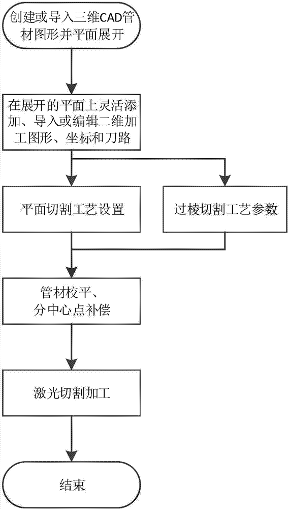
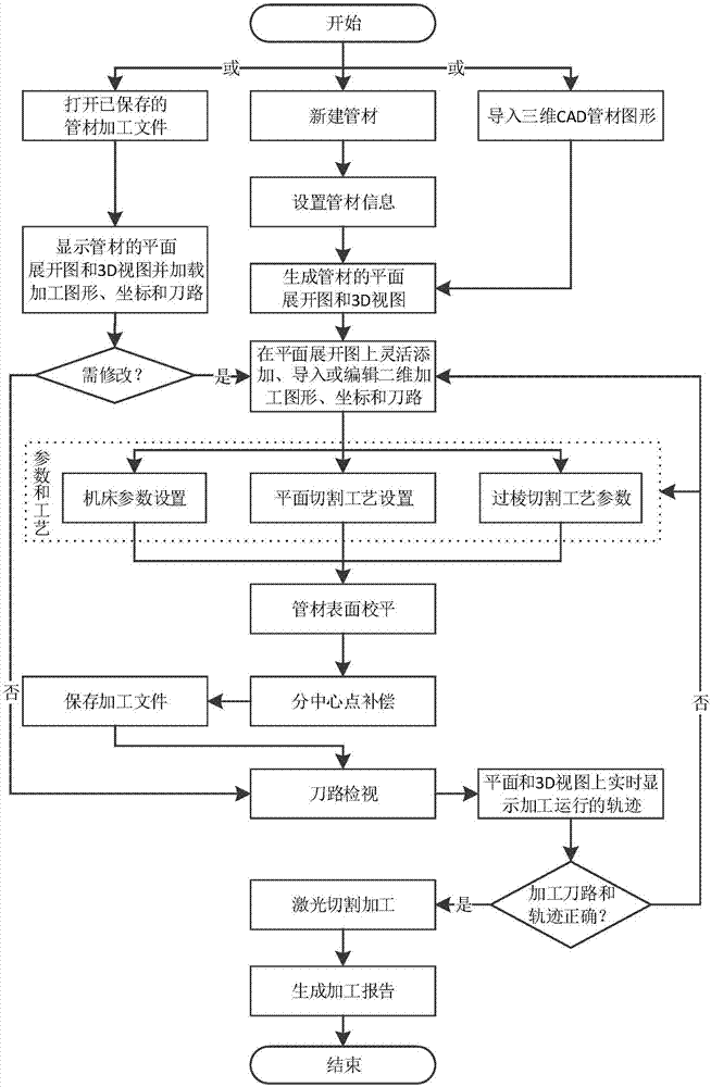
[0034] The method based on laser cutting processing pipes, such as figure 2 shown, including the following steps:

[0035] (1) Generate 3D pipe graphics through computer system;

[0036] (2) Add cutting graphics or import preset cutting graphics, and edit desired processing coordinates and tool paths;

[0037] (3) Confirm the edge cutting process parameter group according to the actual configuration of the laser cutting machine tool;

[0038] (4) Edit the process parameters of laser cutting;

[0039] (5) Calibrate the processed surface of the flat pipe through the computer system;

[0040] (6) Compensation for each side division through the computer system;

[0041] (7) Start processing.

[0042] In a preferred embodiment, the step (1) is specifically:

[0043] Expand and draw the pipe based on the ...


PUM


Abstract

The invention relates to a method for machining a pipe based on laser cutting. The method comprises the following steps that (1) 3D pipe graphics are generated through a computer system; (2) cutting graphics are added or preset cutting graphics are guided, and desired machining coordinates are edited; (3) arris-crossing cutting technology parameter set is confirmed according to actual configuration of a laser cutting machine tool; (4) technology parameters of laser cutting are edited; (5) a machining surface of flat pipe is calibrated through the computer system; (6) score moderate compensation of all sides is conducted through the computer system; and (7) machining is started. By adopting the method for machining the pipe based on the laser cutting, training and using doorsill is lowered, requirements for diversity and visual editing are met in practical machining, the machining accuracy is improved by 70% or more than the industry average, machining sequencing of pipe pieces is supported, utilization rate of materials is optimized, and a wide application range is achieved.

Description

technical field [0001] The invention relates to the technical field of numerical control processing, in particular to the technical field of pipe cutting, and specifically refers to a method for processing pipes based on laser cutting. Background technique [0002] At present, the current pipe cutting processing modes in the field of laser cutting at home and abroad are as follows: figure 1 As shown, first draw the 3D graphics of the pipe in the CAD software, then import the special NC programming software and cover the cutting pattern, and then carry out the routine laser tool path calculation and then process it on the machine. This mode generally has the disadvantages of high threshold for use and training, the one-time generation of the laser tool path (pattern covering) cannot be edited, and the error of pipe size and fixture assembly cannot be effectively compensated, making the effect in practical application It is greatly reduced and cannot effectively meet the dive...

Claims


Application Information

Patent Timeline
Patent Type & Authority Applications(China)
IPC IPC(8): B23K26/38B23K26/70
CPCB23K26/38B23K26/702
Inventor 景梓森丁强郑之开杜全杨开锦黄海燕杨晓斌
Owner SHANGHAI WEIHONG ELECTRONICS TECH
Learn More