
Electric nest structure for fresh air treatment device and fresh air treatment device

A technology of fresh air and air outlet, applied in the field of fresh air equipment, can solve the problems of high manufacturing cost, complex processing technology, secondary pollution of filter elements, etc., and achieve the effect of reducing production cost and flexible assembly.

Pending Publication Date: 2017-08-15
深圳净峰空气净化有限公司
View PDF5 Cites 2 Cited by
  • Summary
  • Abstract
  • Description
  • Claims
  • Application Information

AI Technical Summary

Problems solved by technology

The HEPA filter has the function of filtering dust particles. Activated carbon and other substances are mainly used to absorb toxic and harmful substances such as odors. It is a technology to form a wavy gasket to place and support the filter medium to filter harmful substances. Therefore, this filtration technology can only block harmful substances, and there are problems such as short life of consumables and secondary pollution caused by discarded filter elements.
In addition, the internal components in the existing air treatment devices are usually stamped or injection molded, and the processing technology is complicated and the manufacturing cost is high

Method used


Image

  • Electric nest structure for fresh air treatment device and fresh air treatment device
  • Electric nest structure for fresh air treatment device and fresh air treatment device
  • Electric nest structure for fresh air treatment device and fresh air treatment device

Examples


Embodiment 1

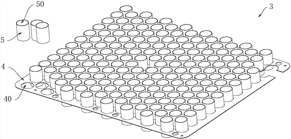
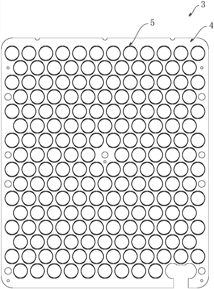
[0026] Such as figure 1 , 2 As shown, an electric nest structure for a fresh air governing device includes a bracket 4, and a plurality of mounting holes 40 distributed in an array are provided on the bracket 4, and metal holes 40 connected to the bracket 4 are provided in the mounting holes. cylinder 5, and the metal cylinder 5 is provided with a cavity 50 for passing through the airflow. Wherein the metal barrel runs through the installation hole on the bracket.

[0027] In the above electric nest structure, since a plurality of mounting holes 40 are provided on the bracket 4, a plurality of metal cylinders 5 can respectively pass through a plurality of mounting holes 40 and be fixed on the bracket 4, thereby forming a honeycomb structure. The nest structure is loaded with DC high voltage, so that a high-voltage electric field is formed at the electric nest structure, and the pollution particles in the air can be adsorbed and separated by using the high-voltage electric fi...

Embodiment 2

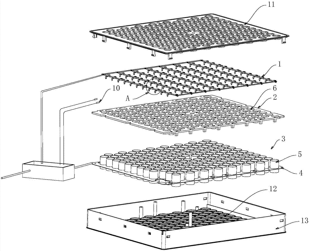
[0030] Such as Figure 1~5 As shown, a fresh air governing device includes a discharge electrode 1, an insulating partition 2, and an electric nest structure 3 in Embodiment 1 arranged sequentially from the wind inlet side to the wind outlet side, and the insulation partition 2 is provided with A plurality of through holes 6, the through holes 6 are aligned with the metal cylinder one by one, a plurality of lugs 7 are formed on the discharge electrode 1, the lugs 7 extend into the through holes 6, the discharge Both the electrode 1 and the electric nest structure 3 are electrically connected to a high-voltage power supply unit 8, and the high-voltage power supply unit 8 is used to provide voltage to the discharge electrode 1 and the electric nest structure 3, so that the discharge electrode 1 and the electric nest structure 3 are formed High-voltage electric field, by which the pollution particles in the air are removed, and the fresh air treatment device also includes a negat...


PUM


Abstract

The invention discloses an electric nest structure for a fresh air treatment device and the fresh air treatment device. The electric nest structure comprises a bracket, the bracket is provided with a plurality of installation holes distributed in an array manner, the installation holes are internally provided with metal barrels in a penetrated manner, the metal barrels are connected with the bracket, and the metal barrels are internally provided with cavities allowing the air flow to penetrate through. The electric nest structure has the advantages of being easy to produce and assemble, low in machining cost, capable of efficiently purifying air and the like.

Description

technical field [0001] The invention relates to fresh air equipment, in particular to an electric nest structure for a fresh air controller and a fresh air controller. Background technique [0002] With the rapid improvement of people's living standards, the awareness of air pollution continues to increase, and the harm of air pollution to human health cannot be ignored. The release of harmful chemical substances is one of them, especially the release of harmful substances contained in indoor and automotive interior parts and decorative materials that are closely related to people's daily life, including plastic and rubber parts and fabrics used in automobiles. Volatile components such as organic solvents, additives, additives contained in materials such as paints, coatings, thermal insulation materials, and adhesives. These pollutants mainly include benzene, toluene, formaldehyde, hydrocarbons, halogenated hydrocarbons, etc. The substances released by the materials in the ...

Claims


Application Information

Patent Timeline
IPC IPC(8): F24F3/16F24F11/00F24F13/28
CPCF24F11/30F24F11/62F24F13/28F24F2110/50F24F11/58F24F8/108F24F8/10F24F8/192F24F8/30
Inventor 白喜宗
Owner 深圳净峰空气净化有限公司
Learn More