Electronic meridian therapeutic apparatus with excessive current prevention

A therapeutic apparatus and oversized technology, applied in physical therapy, artificial respiration, etc., can solve the problems of inability to cut off abnormal current circuits in time, the driving current is not stable enough, and the therapeutic effect is not obvious enough, so as to improve the therapeutic effect, ensure stability, good treatment effect

Inactive Publication Date: 2017-08-18
潍坊大地医疗器械有限公司
9 Cites 4 Cited by

AI-Extracted Technical Summary

Problems solved by technology

[0003] But the existing meridian therapeutic apparatus has the following defects: the therapeutic effect is not obvious enough; the manufacturing cost is high; the meridian therapeutic apparatus that has during treatment will have excessive current or electric leakage accident, so that the health...

Method used

17, remote controller control module and control port, remote controller adopts superheterodyne sound meter frequency stabilization circuit, stable work.
18, intensity control, adopt encoder mode, have single-chip microcomputer control, make knob limitless, adjustab...

Abstract

The invention discloses an electronic meridian therapeutic apparatus with excessive current prevention. The electronic meridian therapeutic apparatus comprises three paths of step-up units, three paths of tank drop units, three paths of relay control units, a current detection unit, a current setting adjustment unit, an overvoltage and overcurrent protection unit, and a tone unit. The electronic meridian therapeutic apparatus is characterized in that the current detection unit comprises a current transformer T1, the tone unit comprises a buzzer U4, the current setting adjustment unit comprises a zener diode Z1 and a sliding resistor R46, the overvoltage and overcurrent protection unit comprises a varistor RV1, a fuse RF1, a fuse RF2, a fuse RF3, and a fuse RF4. The electronic meridian therapeutic apparatus has the advantages that the response speed is fast, an abnormal current loop is timely cut, large current is avoided, alarm is carried out when the current is too large, stable current is maintained, stable driving current can be outputted, the cost of current detection is reduced, the therapeutic effect of the meridian therapeutic apparatus is good, a purpose of dredging meridians can be achieved, the disease cure rate is high, the manufacturing cost is low, and the electronic meridian therapeutic apparatus is safe and reliable.

Application Domain

Artificial respiration

Technology Topic

VaristorDisease +12

Image

  • Electronic meridian therapeutic apparatus with excessive current prevention
  • Electronic meridian therapeutic apparatus with excessive current prevention
  • Electronic meridian therapeutic apparatus with excessive current prevention

Examples

  • Experimental program(1)
  • Effect test(1)

Example Embodiment

[0059] Example 1, such as Figure 1 to Figure 27 As shown, an electronic meridian therapy instrument for preventing excessive current includes a single-chip microcomputer unit. The single-chip microcomputer unit includes a single-chip microcomputer U6. The model of the single-chip microcomputer U6 is IAP 15W4138. The single-chip microcomputer U6 includes pins 1 to 44.
[0060] An electronic meridian therapy instrument for preventing excessive current includes an operational amplifier power supply unit. The operational amplifier power supply unit includes a diode D1 and a diode D2. The diode D1 and the diode D2 are connected in series. The anode connector of the diode D1 is connected to pin 5 of J9. The cathode of diode D1 is connected to +15V, the cathode of diode D2 is connected to pin 5 of J9, the anode of diode D2 is connected to -15V, the cathode of diode D1 is connected to the cathode of diode D3, and the anode of diode D3 is connected to pin 3 of J9, and diode D3 The anode of diode D4 is connected to the cathode of diode D4, the anode of diode D4 is connected to -15V, the cathode of diode D3 is grounded through capacitor EC1, the cathode of diode D3 is grounded through capacitor C1, the cathode of diode D3 is grounded through diode D5, and the cathode of diode D3 is grounded through capacitor C35. Grounding, the anode of diode D4 is grounded through capacitor EC2, the anode of diode D4 is grounded through capacitor C2, the anode of diode D4 is grounded through diode D16, and the anode of diode D4 is grounded through capacitor C36.
[0061] The electronic meridian therapy instrument also includes a three-way adjustment treatment intensity output unit, the three-way adjustment treatment intensity output unit includes an A-way adjustment treatment intensity output unit, a B-way adjustment treatment intensity output unit, and a C-way adjustment treatment intensity output unit.
[0062] The A-channel adjustment treatment intensity output unit includes integrated circuit U7. Pin 1 of integrated circuit U7 is connected to pin 5 of microcontroller U6, pin 2 of integrated circuit U7 is connected to pin 6 of microcontroller U6, and pin 3 of integrated circuit U7 is connected via resistor R3. +5V, the 3rd pin of the integrated circuit U7 is grounded via the resistor R4, the 3rd pin of the integrated circuit U7 is connected to the total waveform generator U16 via the capacitor C17, the 4 pin of the integrated circuit U7 is grounded, the 5th pin of the integrated circuit U7 is connected to the capacitor C19 via the resistor R5 The other end of capacitor C19 is grounded through capacitor C23, the other end of capacitor C19 is grounded through resistor R25, and the other end of capacitor C19 is connected to pin 1 of power amplifier circuit U1. The model of power amplifier circuit U1 is TDA2030A, and pin 2 of power amplifier circuit U1 Connect the resistor R31 and the capacitor EC4 in series to the ground, the 2 pin of the power amplifier circuit U1 is connected to the 4 pin of the power amplifier circuit U1 via the resistor R26, the 3 pin of the power amplifier circuit U1 is connected to -15V, and the 3 pin of the power amplifier circuit U1 is connected to the power amplifier circuit U1 via the diode D11. Pin 4 of the power amplifier circuit U1 is connected to the three-way boost unit, pin 4 of the power amplifier circuit U1 is connected to the pin 5 of the power amplifier circuit U1 via the diode D6, and pin 5 of the power amplifier circuit U1 is connected to +15V.
[0063] The B-channel adjustment treatment intensity output unit includes integrated circuit U8, one pin of integrated circuit U8 is connected to pin 8 of single-chip microcomputer U6, pin 2 of integrated circuit U8 is connected to pin 9 of microcontroller U6, and pin 3 of integrated circuit U8 is connected via resistor R7 +5V, pin 3 of integrated circuit U8 is grounded through resistor R8, pin 3 of integrated circuit U8 is connected to total waveform generator U16 through capacitor C18, pin 4 of integrated circuit U8 is grounded, pin 5 of integrated circuit U8 is connected to capacitor C20 through resistor R9 The other end of the capacitor C20 is grounded through the capacitor C24, the other end of the capacitor C20 is grounded through the resistor R27, the other end of the capacitor C20 is connected to pin 1 of the power amplifier circuit U2, the model of the power amplifier circuit U2 is TDA2030A, and the power amplifier circuit U2’s pin 2 Connect the resistor R32 and the capacitor EC5 in series to the ground, the 2 pin of the power amplifier circuit U2 is connected to the 4 pin of the power amplifier circuit U2 via the resistor R28, the 3 pin of the power amplifier circuit U2 is connected to -15V, and the 3 pin of the power amplifier circuit U2 is connected to the power amplifier circuit U2 via the diode D13. Pin 4 of the power amplifier circuit U2 is connected to the three-way booster unit, pin 4 of the power amplifier circuit U2 is connected to the pin 5 of the power amplifier circuit U2 via the diode D12, and pin 5 of the power amplifier circuit U2 is connected to +15V.
[0064] The C-channel adjustment treatment intensity output unit includes integrated circuit U9. Pin 1 of integrated circuit U9 is connected to pin 11 of microcontroller U6, pin 2 of integrated circuit U9 is connected to pin 12 of microcontroller U6, and pin 3 of integrated circuit U9 is connected via resistor R18. +5V, the 3rd pin of the integrated circuit U9 is grounded through the resistor R19, the 3rd pin of the integrated circuit U9 is connected to the total waveform generator U16 through the capacitor C21, the 4th pin of the integrated circuit U9 is grounded, the 5th pin of the integrated circuit U9 is connected to the capacitor C22 through the resistor R20 The other end of capacitor C22 is grounded through capacitor C25, the other end of capacitor C22 is grounded through resistor R29, and the other end of capacitor C22 is connected to pin 1 of power amplifier circuit U3. The model of power amplifier circuit U3 is TDA2030A, and pin 2 of power amplifier circuit U3 Connect the resistor R33 and the capacitor EC6 in series to the ground, the 2 pin of the power amplifier circuit U3 is connected to the 4 pin of the power amplifier circuit U3 via the resistor R30, the 3 pin of the power amplifier circuit U3 is connected to -15V, and the 3 pin of the power amplifier circuit U3 is connected to the power amplifier circuit U3 via the diode D15. Pin 4 of the power amplifier circuit U3 is connected to the three-way booster unit, pin 4 of the power amplifier circuit U3 is connected to the pin 5 of the power amplifier circuit U3 via the diode D14, and pin 5 of the power amplifier circuit U3 is connected to +15V.
[0065] The models of the integrated circuit U7, integrated circuit U8 and integrated circuit U9 are all X9C103SI.
[0066] The electronic meridian therapeutic apparatus also includes a three-way boosting unit, which includes an A-way boosting unit, a B-way boosting unit, and a C-way boosting unit.
[0067] The C-channel step-up unit includes a transformer U10. Pin 1 of the transformer U10 is connected to pin 4 of the power amplifier circuit U3 in the C-channel adjustment treatment intensity output unit. Pin 1 of the transformer U10 is grounded through a series resistor R34 and a capacitor C26. Pin 2 is grounded, pin 3 of transformer U10 is connected to the current detection unit, pin 4 of transformer U10 is connected to pin 3 of relay K1, pin 1 of relay K1 is connected to pin 2 of relay K1 via diode D17, diode D17 is rectifier diode 1N4007, relay K1 Pin 2 of the relay K1 is connected to +5V, pin 1 of the relay K1 is connected to the collector of the transistor Q2 in the three-way relay control unit, and pin 4 of the relay K1 is connected to the fuse RF4 in the terminal J8;
[0068] The B-way step-up unit includes a transformer U11, the 1 pin of the transformer U11 is connected to the 4 pin of the power amplifier circuit U2 in the B-way adjustment treatment intensity output unit, the 1 pin of the transformer U11 is grounded through the series resistor R35 and the capacitor C27, the transformer U11 Pin 2 is grounded, pin 3 of transformer U11 is connected to the current detection unit, pin 4 of transformer U11 is connected to pin 3 of relay K2, pin 1 of relay K2 is connected to pin 2 of relay K2 via diode D18, diode D18 is rectifier diode 1N4007, relay K2 Pin 2 of the relay K2 is connected to +5V, pin 1 of the relay K2 is connected to the collector of the transistor Q3 in the three-way relay control unit, and pin 4 of the relay K2 is connected to the fuse RF3 in the terminal J8;
[0069] The A-way boost unit includes a transformer U12, the 1 pin of the transformer U12 is connected to the 4 pin of the power amplifier circuit U1 in the A-channel adjustment treatment intensity output unit, the 1 pin of the transformer U12 is grounded through the series resistor R36 and the capacitor C28, and the transformer U12 Pin 2 is grounded, pin 3 of transformer U12 is connected to the current detection unit, pin 4 of transformer U12 is connected to pin 3 of relay K3, pin 1 of relay K3 is connected to pin 2 of relay K3 via diode D19, diode D19 is rectifier diode 1N4007, relay K3 Pin 2 of the relay K3 is connected to +5V, pin 1 of the relay K3 is connected to the collector of the transistor Q4 in the three-way relay control unit, and pin 4 of the relay K3 is connected to the fuse RF2 in the terminal J8;
[0070] The models of the relay K1, the relay K2, and the relay K3 are PA1a-5V.
[0071] The electronic meridian therapeutic apparatus also includes a three-way tank dropping unit, which includes a path A tank dropping unit, a path B tank dropping unit, and a path C tank dropping unit.
[0072] The A-way tank drop unit includes a photocoupler U13, pin 1 of the photocoupler U13 is connected to pin 2 of the photocoupler U13 via a diode D22, pin 1 of the photocoupler U13 is connected to the current detection unit, and pin 2 of the photocoupler U13 Pin 2 of terminal J8, pin 3 of photocoupler U13 is grounded, pin 4 of photocoupler U13 is connected to +5V via resistor R6, pin 4 of photocoupler U13 is connected to pin 38 of microcontroller U6;
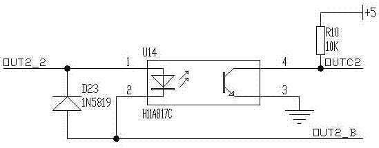
[0073] The B-way tank drop unit includes a photocoupler U14, pin 1 of the photocoupler U14 is connected to pin 2 of the photocoupler U14 via a diode D23, pin 1 of the photocoupler U14 is connected to the current detection unit, and pin 2 of the photocoupler U14 Pin 3 of terminal J8, pin 3 of photocoupler U14 is grounded, pin 4 of photocoupler U14 is connected to +5V via resistor R10, pin 4 of photocoupler U14 is connected to pin 37 of microcontroller U6;
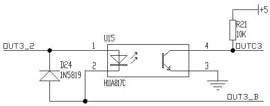
[0074] The C-circuit can drop unit includes a photocoupler U15, pin 1 of the photocoupler U15 is connected to pin 2 of the photocoupler U15 via a diode D24, pin 1 of the photocoupler U15 is connected to the current detection unit, and pin 2 of the photocoupler U15 The pin is connected to the 5 pin of the terminal J8, the 3 pin of the photocoupler U15 is grounded, the 4 pin of the photocoupler U15 is connected to +5V via the resistor R21, and the 4 pin of the photocoupler U15 is connected to the 35 pin of the microcontroller U6.
[0075] The models of the photocoupler U13, photocoupler U14, and photocoupler U15 are H11A817C.
[0076] The electronic meridian therapy instrument also includes a three-way relay control unit, and the three-way relay control unit includes an A-way relay control unit, a B-way relay control unit, and a C-way relay control unit.
[0077] The circuit C relay control unit includes a triode Q2, the emitter of the triode Q2 is grounded, the base of the triode Q2 is grounded via a resistor R42, and the base of the triode Q2 is connected to the 44 pin of the single-chip microcomputer U6 via a resistor R39;
[0078] The B relay control unit includes a triode Q3, the emitter of the triode Q3 is grounded, the base of the triode Q3 is grounded through a resistor R43, and the base of the triode Q3 is connected to the 36 pin of the single-chip microcomputer U6 through a resistor R40;
[0079] The circuit A relay control unit includes a triode Q4, the emitter of the triode Q4 is grounded, the base of the triode Q4 is grounded through a resistor R44, and the base of the triode Q4 is connected to the 34 pin of the single-chip microcomputer U6 through a resistor R41.
[0080] The models of the triode Q2, the triode Q3, and the triode Q4 are 9013.
[0081] The electronic meridian therapy instrument also includes a single-chip power supply unit. The single-chip power supply unit includes a power supply regulator chip U5. The model of the power supply regulator chip U5 is LM2575S-5.0. Pin 1 of the power supply regulator chip U5 is grounded through a transient suppression diode D20. The model of transient suppression diode D20 is P6KE36CA. Pin 1 of power regulator chip U5 is grounded through capacitor C3, pin 1 of power regulator chip U5 is grounded through capacitor EC3, pin 1 of power regulator chip U5 is connected in series with diode D9 and Diode D10 is grounded, pin 1 of the power supply regulator chip U5 is grounded through the series diode D7 and diode D8. The models of diode D7, diode D8, diode D9 and diode D10 are all 1N4007, and pin 1 of power regulator chip U5 is connected to diode D7. Pin 2 of connector J9, pin 1 of power regulator chip U5 is connected to pin 1 of connector J9 via diode D9, pin 2 of power regulator chip U5 is grounded via diode D21, the model of diode D21 is 1N5819, power regulator Pin 2 of the chip U5 is connected to one end of the inductor L1, the other end of the inductor L1 is grounded through the capacitor C15, the other end of the inductor L1 is grounded through the capacitor C16, the other end of the inductor L1 is connected to +5V, and the other end of the inductor L1 is grounded through the capacitor CB1. The other end of the inductor L1 is connected to pin 4 of the power regulator chip U5, and the pins 3 and 5 of the power regulator chip U5 are grounded respectively.
[0082] The electronic meridian therapy instrument also includes a communication unit, the communication unit includes a connector J13, the model of the connector J13 is XH2.54-3P, the 3 pin of the connector J13 is grounded, and the 3 pin of the connector J13 is connected with transients. One end of diode DS1 and the other end of transient diode DS1 are connected to pin 18 of MCU U6. The other end of transient diode DS1 is connected to one end of fuse RS1. The other end of fuse RS1 is connected to pin 2 of connector J13, and pin 1 of connector J13 is connected to a fuse. One end of RS2, the other end of fuse RS2 is connected to pin 19 of single-chip microcomputer U6, the other end of fuse RS2 is connected to one end of transient diode DS2, and the other end of transient diode DS2 is grounded.
[0083] The 2 pin of the connector J13 is connected to the 2 pin of the interface control chip J2, and the 3 pin of the connector J13 is connected to the 3 pin of the interface control chip J2.
[0084] The model of the interface control chip J2 is 2510-4, the interface control chip J2 includes pins 1-4, pin 1 of the interface control chip J2 is connected to a 5V power supply, and pin 4 of the interface control chip J2 is grounded.
[0085] The models of the transient diode DS1 and DS2 are P4SMA18CA, and the models of the fuse RS1 and RS2 are FSMD020-1210.
[0086] The electronic meridian therapy instrument also includes a current detection unit, the current detection unit includes a current transformer T1, pin 1 of the current transformer T1 is connected to pin 3 of the transformer U12 of the A boost unit, and pin 2 of the current transformer T1 The pin is connected to pin 1 of the photocoupler U15 of the tank drop unit of circuit A, the model of the photocoupler U15 is H11A817C, the pin 3 of the current transformer T1 is connected to pin 3 of the transformer U11 of the B boost unit, and the current transformer Pin 4 of T1 is connected to pin 1 of the photocoupler U14 of the B circuit drop unit. The model of the photocoupler U14 is H11A817C. Pin 5 of the current transformer T1 is connected to pin 3 of the transformer U10 of the C circuit boost unit. Pin 6 of the current transformer T1 is connected to pin 1 of the photocoupler U13 of the C-drop unit. The model of the photocoupler U13 is H11A817C; pin 7 of the current transformer T1 is connected to the cathode of the diode D27 and the anode of the diode D25 The 8 pin of current transformer T1 is connected to the cathode of diode D28 and the anode of diode D26. The anode of diode D27 is connected to the anode of diode D28. The cathode of diode D25 is connected to the cathode of diode D26. The cathode of diode D26 is connected to the current device. Determine the adjustment unit.
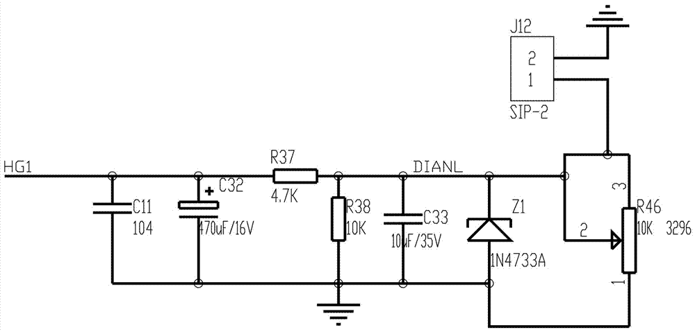
[0087] The electronic meridian therapy instrument also includes a current setting adjustment unit. The current setting adjustment unit includes a capacitor C11. One end of the capacitor C11 is connected to one end of the capacitor C32 and one end of the resistor R37, and is connected to the current detection unit. The other end of the capacitor C11 is grounded. The other end of C32 is grounded, the other end of resistor R37 is connected to one end of resistor R38, one end of capacitor C33, one end of Zener diode Z1, and the second end of sliding resistor R46. The other end of resistor R38 is grounded, the other end of capacitor C33 is grounded, and the other end of Zener diode Z1. Grounding, the 2 pins of the sliding resistor R46 are connected to the 3 pins of the sliding resistor R46, the 1 pin of the sliding resistor R46 is grounded, the 3 pins of the sliding resistor R46 are connected to the 1 pin of the single row seat J12, and the 2 feet of the single row seat J12 are grounded.
[0088] The electronic meridian therapy instrument also includes a waveform generating unit, the waveform generating unit includes a total waveform generator U16, 1 pin of the total waveform generator U16 is connected with an operational amplifier power supply unit, and 2 pins of the total waveform generator U16 are connected with a sliding Pin 3 of resistor R22, pin 3 of sliding resistor R22 and pin 1 of sliding resistor R22 are connected, pin 2 of sliding resistor R22 is connected to the three-way adjustment treatment intensity output unit, pin 3 of total waveform generator U16 is grounded, total waveform generator Pin 4 of U16 is connected to 5V power supply, pin 5 of total waveform generator U16 is connected to pin 1 of microcontroller U6, pin 6 of total waveform generator U16 is connected to pin 2 of microcontroller U6, pin 7 of total waveform generator U16 is connected to microcontroller U6 3 feet.
[0089] The model of the total waveform generator U16 is XQ-1, which includes a waveform generating circuit, a waveform calibration circuit, an input control circuit, and a waveform output circuit. The input control circuit outputs signals to the waveform generation circuit, and the waveform generation circuit outputs a waveform calibration circuit. , The waveform output circuit connects the output signal to the waveform generation circuit. It is a circuit composed of PCB circuit boards, resistors, capacitors, digital integrated chips, etc. It is poured with epoxy resin to become an independent integrated unit device, a total waveform generator Pin 1 of U16 is connected by the waveform calibration circuit, and the waveform calibration circuit compares and calibrates the waveform generating circuit. The 5, 6, and 7 pins of the total waveform generator U16 are connected by the input control circuit to control the waveform generation and reach the treatment center. For the required waveform, pin 2 of the total waveform generator U16 is the waveform output circuit port, which can generate AC low-frequency basic waves, and can generate modulated AC waveforms according to treatment needs under the control of the single-chip microcomputer.
[0090] The waveform generation circuit, waveform calibration circuit, input control circuit, and waveform output circuit are well-known circuits, and any circuit connection that realizes waveform generation, waveform calibration, input control, and waveform output is acceptable.
[0091] The electronic meridian therapy instrument also includes a waveform output control unit, the waveform output control unit includes a terminal J6, the model of the terminal J6 is XH2.54-5P, the terminal J6 includes 1-5 pins, and the terminal J6 is 1 One end of the resistor R48 is connected to the pin, the other end of the resistor R48 is connected to a 5V power supply, the 2 pin of the terminal J6 is grounded, the 3 pin of the terminal J6 is connected to one end of the resistor R11, the other end of the resistor R11 is grounded, and the 3 pin of the terminal J6 is connected to the microcontroller Pin 20 of U6, pin 4 of terminal J6 are grounded, pin 5 of terminal J6 is connected to one end of resistor R45, and the other end of resistor R45 is connected to a 5V power supply.
[0092] The electronic meridian therapy instrument also includes a button unit, the button unit includes a terminal J1, the model of the terminal J1 is XH2.54-6P, the terminal J6 includes pins 1-6, and one pin of the terminal J6 is connected to one end of a resistor RK1 , The other end of the resistor RK1 is connected to a 5V power supply, the 2 pin of the terminal J6 is connected to one end of the resistor RK2, the other end of the resistor RK2 is connected to a 5V power source, the 3 pin of the terminal J6 is connected to one end of the resistor RK3, and the other end of the resistor RK3 is connected to 5V For power supply, one end of resistor RK4 is connected to pin 4 of terminal J6, the other end of resistor RK4 is connected to a 5V power source, pin 5 of terminal J6 is connected to one end of resistor RK5, and the other end of resistor RK5 is connected to 5V power, pin 6 of terminal J6 One end of resistor RK6 is connected, and the other end of resistor RK6 is connected to 5V power supply; pin 1 of terminal J6 is connected to pin 27 of MCU U6, pin 2 of terminal J6 is connected to pin 26 of MCU U6, and pin 3 of terminal J6 is connected with The pin 25 of the single-chip microcomputer U6 is connected, the pin 3 of the terminal J4 is connected with the pin 24 of the single-chip U6, the pin 5 of the terminal J6 is connected with the pin 23 of the single-chip microcomputer U6, and the pin 6 of the terminal J6 is connected with the 22 pin of the single-chip U6.
[0093] The electronic meridian therapy instrument also includes a remote control unit. The remote control unit includes a single-row seat J11. The single-row seat J11 includes pins 1-8. Pin 1 of the single-row seat J11 is grounded and connected to one end of a capacitor C11. The other end of C11 is connected to 5V power supply, pin 2 of J11 is connected to 5V power supply, pin 3 of J11 is connected to pin 39 of MCU U6, pin 4 of J11 is connected to pin 40 of MCU U6, single row Pin 5 of J11 is connected to Pin 41 of MCU U6, Pin 6 of J11 is connected to Pin 42 of MCU U6, Pin 7 of J11 is connected to Pin 43 of MCU U6, Pin 8 of J11 is connected to switch One end of S1 is connected to one end of resistor R47, the other end of switch S1 is grounded, and the other end of resistor R47 is connected to a 5V power supply.
[0094] The electronic meridian therapy instrument also includes an overvoltage and overcurrent protection unit. The overvoltage and overcurrent protection unit includes a varistor RV1. The model of the varistor RV1 is TVR14561. One end of the varistor RV1 is connected to AC220V voltage. The other end of the varistor RV1 is connected with pin 2 of connector J14, pin 1 of connector J3, and pin 2 of connector J4. The models of connector J14, connector J3, and connector J4 are CH5.08-2P. Pin 1 of plug-in J4 is connected to AC220V voltage, pin 1 of connector J14 is connected to pin 2 of connector J3, pin 2 of connector J3 is connected to one end of fuse RF1, the model of fuse RF1 is FRV016-240F, and the other end of fuse RF1 is connected Enter AC220V voltage.
[0095] The overvoltage and overcurrent protection unit includes terminal J8, the model of terminal J8 is XH2.54-6P, terminal J8 includes pins 1-6, pin 1 of terminal J8 is connected to one end of fuse RF4, and the other end of fuse RF4 is connected C-way boost unit, the 2 pin of terminal J8 is connected to the C-way tank drop unit, the 3 pin of terminal J8 is connected to the B-way tank drop unit, the 4 pin of terminal J8 is connected to one end of fuse RF3, and the other end of fuse RF3 is connected to way B For booster unit, the 5-pin of terminal J8 is connected to the A-way tank drop unit, the 6-pin of terminal J8 is connected to one end of the fuse RF2, and the other end of the fuse RF2 is connected to the A-way boost unit.
[0096] The models of the fuse RF2, the fuse RF3, and the fuse RF4 are FRV005-240F.
[0097] The electronic meridian therapy instrument also includes terminal J7, the model of terminal J7 is XH2.54-9P, terminal J7 includes pins 1-9, pin 1 of terminal J7 is connected to pin 33 of microcontroller U6, and terminal J7 Pin 2 is grounded, pin 3 of terminal J7 is connected to pin 32 of MCU U6, pin 4 of terminal J7 is connected to pin 31 of MCU U6, pin 5 of terminal J7 is grounded, pin 6 of terminal J7 is connected to pin 30 of MCU U6 , Pin 7 of terminal J7 is connected to pin 29 of MCU U6, pin 8 of terminal J7 is grounded, pin 9 of terminal J7 is connected to pin 28 of MCU U6; pin 9 of terminal J7 is connected to one end of resistor R12, resistor R12 is another One end is connected to the 5V power supply, the 7th pin of the terminal J7 is connected to one end of the resistor R13, the other end of the resistor R13 is connected to the 5V power supply, the 6th pin of the terminal J7 is connected to one end of the resistor R14, and the other end of the resistor R14 is connected to the 5V power supply. Pin 4 of J7 is connected to one end of resistor R15, the other end of resistor R15 is connected to 5V power supply, pin 3 of terminal J7 is connected to one end of resistor R16, the other end of resistor R16 is connected to 5V power source, pin 1 of terminal J7 is connected to resistor R17 On one end, the other end of resistor R17 is connected to a 5V power supply.
[0098] The electronic meridian therapy instrument also includes a connector J9, the model of the connector J9 is CH3.96-5P, the connector J9 includes 1-5 pins, and the connector J9 is connected to the operational amplifier power supply unit and the single-chip microcomputer power supply unit.
[0099] The electronic meridian therapy instrument also includes a prompt sound unit, the prompt sound unit includes a buzzer U4, pin 1 of the buzzer U4 is connected to a 5V power supply, and pin 2 of the buzzer U4 is connected to the collector of the transistor Q1, The emitter of the transistor Q1 is grounded, the base of the transistor Q1 is connected to one end of the resistor R1 and one end of the resistor R2, the other end of the resistor R1 is connected to pin 21 of the single-chip microcomputer U6, and the other end of the resistor R2 is grounded.
[0100] Description of the circuit work flow of the meridian comprehensive treatment instrument:
[0101] 1. The machine is connected by the character plug power cord with 220V mains power supply. The host has a power socket. After using the machine, the power cord is removed and returned to its place, which is flexible and neat.
[0102] 2. The mains power is protected by a series fuse, equipped with a 200 mA fuse tube. Then through the button-type self-locking switch, the switch has an on-off LED indicator.
[0103] 3. Enter the circuit board, and connect a varistor TVR14561 in parallel to absorb the surge voltage to prevent high voltage and lightning strikes, and play a role in protecting the subsequent circuit.
[0104] 4. Connect a fuse FRV016-240F in series to protect the device from damage when the fault current increases in the subsequent circuit.
[0105] 5. Enter the isolation transformer, which can withstand 4000V voltage and is isolated from the earth to prevent electric shock. Output two sets of voltages, one set provides 9V voltage, and one set provides dual 15V voltages for different circuit needs.
[0106] 6. The dual 15V power supplies are bridge rectified, stabilized, filtered, and protected to supply power to 3 arithmetic units.
[0107] 7. The 9V power supply is bridge rectified, stabilized, filtered, and then connected to a transient suppression diode P6KE36CA. When the two ends of the transient suppression diode are subjected to instantaneous high-energy impact, it can achieve extremely high speed (up to 1*10-12 seconds) to reduce its impedance suddenly, and absorb a large current at the same time, and clamp the voltage between its two ends to a predetermined value, so as to ensure that the subsequent circuit chips are protected from transient high-energy impacts. damage.
[0108] 9. It is stabilized by the integrated voltage stabilizing module LM25758-5.0. This stabilizing block has a large current without an external heat sink. It is directly soldered to the PCB board and filtered to provide power to the subsequent circuit.
[0109] 10. The total waveform generator U16 can generate AC low-frequency basic waves, and can generate modulated AC waveforms according to the treatment needs under the control of the single-chip microcomputer.
[0110] 11. The signal of channel A is moved up by the zero point of the waveform to the digital potentiometer X9C103S1, which controls the intensity of treatment under the control of the single-chip microcomputer.
[0111] 12. The operational amplifier is an energy conversion device combined with a step-up transformer to provide sufficient therapeutic energy as required. The output is controlled by the relay, and the B road and C road are the same as above.
[0112] 13. The output signal passes through the signal detection circuit of the optocoupler combination to provide the single-chip microcomputer with tank drop information.
[0113] 14. Through the current detection circuit, the current information during treatment is provided to the single-chip microcomputer to deal with when the current exceeds the limit.
[0114] 15. The current transformer is a conversion device for three-channel therapeutic current, which can perform combined detection of single-channel, two-channel, three-channel, and current.
[0115] 16. There is also a current setting adjustment circuit and a current setting limit circuit. Overcurrent protection circuit FRV005-240F during output. Program sintering serial port and protection circuit.
[0116] 17. The remote control module and control port, the remote control adopts a superheterodyne sound meter frequency stabilization circuit, which works stably.
[0117] 18. Intensity control adopts encoder mode, with single-chip microcomputer control, which makes the knob unlimited and adjustable speed.
[0118] 19. Waveform control input port circuit. Perform waveform output control.
[0119] 20. The voice prompt circuit provides voice prompts on the working status of the treatment device.
[0120] 22. Single-chip IAP15W413S, to control the functions of the whole machine.
[0121] Turn on the power switch, the power indicator light is on, the single-chip microcomputer starts to run, the display screen is on, and the treatment time is ten minutes, and the time is still. The ABC three-way intensity bar is displayed as zero, and the Lojo icon is displayed, which will always be displayed in the future. Display treatment mode: continuous, with a long tone prompt.
[0122] When the intensity knob is rotated, the display bar segment is correspondingly displayed, the relay is closed, the treatment time countdown starts to display, and a prompt sound is emitted. The remote control has the same function as the knob.

PUM

no PUM

Description & Claims & Application Information

We can also present the details of the Description, Claims and Application information to help users get a comprehensive understanding of the technical details of the patent, such as background art, summary of invention, brief description of drawings, description of embodiments, and other original content. On the other hand, users can also determine the specific scope of protection of the technology through the list of claims; as well as understand the changes in the life cycle of the technology with the presentation of the patent timeline. Login to view more.

Similar technology patents

Four-rotor aircraft safety control method based on high-order disturbance observer

ActiveCN110320925AEliminate modeling errorsGuaranteed stability
Owner:NANJING UNIV OF AERONAUTICS & ASTRONAUTICS

Complete locating device for total hip arthroplsty

PendingCN107149490AReduce the chance and degree of loosening or saggingGuaranteed stability
Owner:汤向阳

Classification and recommendation of technical efficacy words

Why Eureka
Try Eureka