Bionic stirring machine for injection grout, hybrid power bionic stirring system and slurrying method of hybrid power bionic stirring system

A mixer and grouting technology, applied in the directions of mixing operation control, mixing operation control device, cement mixing device, etc., can solve the problem that it is difficult to quantitatively control the amount of slurry material, the performance of the slurry does not meet the expected requirements, the environment and ecology. Adverse effects and other problems, to achieve the effect of improving supply efficiency and quality, easy maintenance, and easy pulping

Active Publication Date: 2017-08-18
CHENGDU UNIVERSITY OF TECHNOLOGY
View PDF5 Cites 4 Cited by
  • Summary
  • Abstract
  • Description
  • Claims
  • Application Information

AI Technical Summary

Problems solved by technology

[0006] When carrying out grouting operations, especially in the field, due to the relatively harsh construction conditions, it is sometimes impossible to connect to municipal power, which leads to relatively power consumption problems Difficult to solve, the usual way is to use diesel / gasoline generators to generate power independently. On the one hand, it needs to consume a lot of fossil fuels such as diesel / gasoline, which leads to higher cost of grouting operations. On the other hand, diesel / gasoline is emitted as fossil fuels after combustion To a certain extent, the pollutants released will also have adverse effects on the environment and ecology.
In addition, the existing traditional mixing and pulping operation basically involves pouring cement powder (ash), water and admixtures into the mixing tank manually from the same inlet. Due to improper operation and other reasons, the slurry material is easily partially dropped and not added to the mixing tank, which will make it difficult to achieve quantitative control of the amount of slurry material added, resulting in the performance of the slurry prepared by mixing with the mixer at the grouting site. The performance of the slurry prepared in the room is inconsistent, that is, the performance of the slurry prepared by stirring the mixer on site cannot meet the expected requirements

Method used


Image

  • Bionic stirring machine for injection grout, hybrid power bionic stirring system and slurrying method of hybrid power bionic stirring system
  • Bionic stirring machine for injection grout, hybrid power bionic stirring system and slurrying method of hybrid power bionic stirring system
  • Bionic stirring machine for injection grout, hybrid power bionic stirring system and slurrying method of hybrid power bionic stirring system

Examples


Embodiment Construction

[0081] The specific embodiments of the present invention are described below so that those skilled in the art can understand the present invention, but it should be clear that the present invention is not limited to the scope of the specific embodiments. For those of ordinary skill in the art, as long as various changes Within the spirit and scope of the present invention defined and determined by the appended claims, these changes are obvious, and all inventions and creations using the concept of the present invention are included in the protection list.

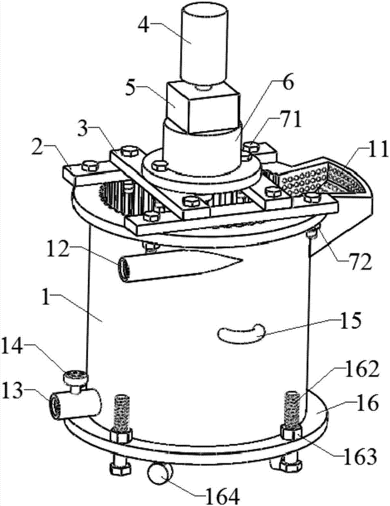
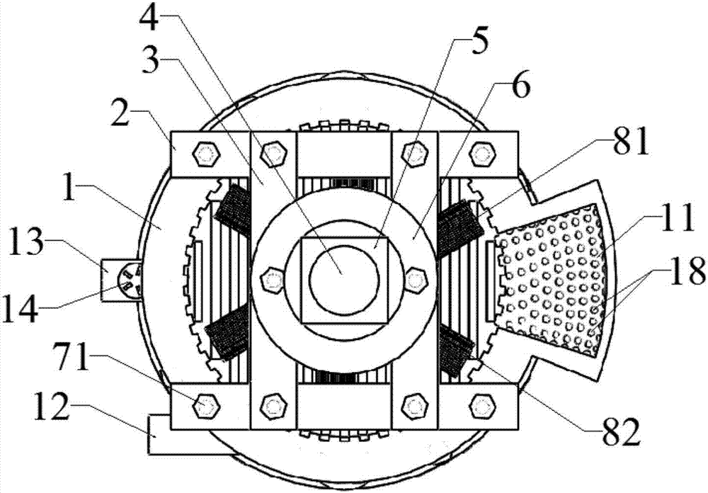
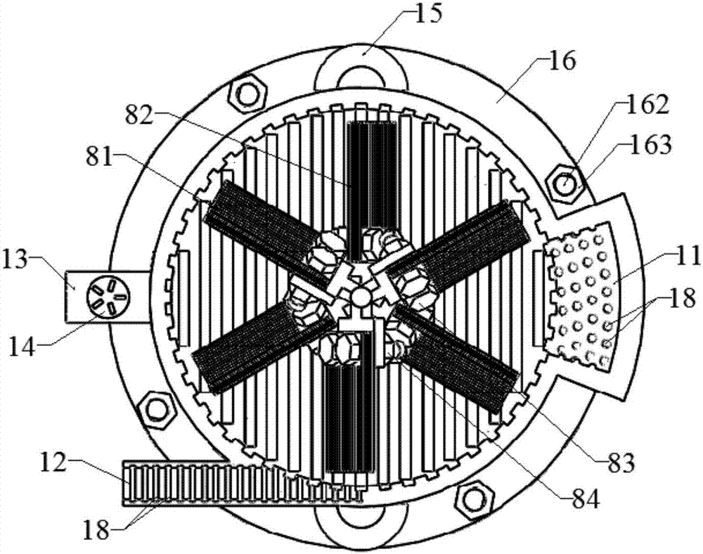
[0082] Such as Figure 1 to Figure 6 As shown, the bionic mixer for grouting includes a mixing tank 1 with a feed inlet and a slurry outlet pipe 13, and the bottom surface of the mixing bucket 1 is a slope 17 facing the slurry outlet pipe 13, where the bottom surface of the mixing bucket 1 is The inclination angle is 5°-35°, so that the slurry in the cavity of the mixing tank 1 has a tendency to flow to the slurry outlet pi...


PUM


Abstract

The invention discloses a bionic stirring machine for injection grout, a hybrid power bionic stirring system and a slurrying method of the hybrid power bionic stirring system. The bionic stirring machine for injection grout comprises a stirring tank with a feed inlet and a slurry discharge pipe. The bottom face of the stirring tank is an inclined face which is inclined towards the slurry discharge pipe. The upper end of the stirring tank is fixedly provided with a power portion through a supporting frame. The power output end of the power portion is connected with a stirring shaft in the stirring tank. A stirring paddle is vertically or obliquely arranged on the stirring shaft. When the stirring paddle is obliquely arranged on the stirring shaft, the inclination direction of the stirring paddle is opposite to the rotation direction of the stirring shaft. The inner surface of the stirring tank, the inner surface of the feed inlet, the inner surface of the slurry discharge pipe and the stirring paddle are each provided with a plurality of bionic non-smooth units. The superficial area of faces, making contact with the bionic non-smooth units, of the stirring tank, the feed inlet and the slurry discharge pipe is 20-50% of the superficial area of the inner surfaces of the components, and the superficial area of the faces, making contact with the stirring paddle, of all the bionic non-smooth units on the stirring paddle is 20-60% of the superficial area of all surfaces of the stirring paddle.

Description

technical field [0001] The invention relates to a machine tool used in the grouting field, in particular to a bionic mixer for grouting, a hybrid bionic mixing system and a slurrying method thereof. Background technique [0002] Grouting (Injection Grout), also known as grouting (Grouting), is a grout with coagulation ability prepared from certain specific materials in a certain proportion, and is sent to Pour into the cracks, pores or caves in the formation (rock and soil), and make it diffuse, gel or solidify, so as to achieve the purpose of strengthening the formation or preventing seepage and plugging; mainly including static pressure grouting (Static Pressure Grouting) And high pressure jet grouting (High Pressure Jet Grouting) and other types. At present, grouting technology has been widely used in rock and soil reinforcement and anti-seepage in water conservancy and hydropower, transportation, construction, mining and other projects, as well as slope protection, sand...

Claims


Application Information

Patent Timeline
Patent Type & Authority Applications(China)
IPC IPC(8): B28C5/16B28C5/08B28C7/04B28C7/06B28C7/12E02D15/02
CPCE02D15/02B28C5/0806B28C5/0831B28C5/0856B28C5/0862B28C5/16B28C7/0404B28C7/067B28C7/12
Inventor 温继伟裴向军王文臣袁进科张文何智浩杜野任童
Owner CHENGDU UNIVERSITY OF TECHNOLOGY
Why Eureka
Try Eureka