Anaerobic biological decalcification system and method

A technology of anaerobic biology and anaerobic sludge, which is applied in anaerobic biological decalcification system and decalcification field, can solve the problems of high energy consumption, high cost of decalcification treatment, complex structure of sewage decalcification device, etc., and achieve system investment Large, low-cost biological decalcification, the effect of improving removal efficiency and system stability

Pending Publication Date: 2017-08-18
山东环发科技开发有限公司
View PDF3 Cites 5 Cited by
  • Summary
  • Abstract
  • Description
  • Claims
  • Application Information

AI Technical Summary

Problems solved by technology

[0007] Aiming at the deficiencies of the prior art, especially the defects of complex structure, high decalcification treatment cost and high energy consumption of the existing sewage decalcification device, the present invention provides an anaerobic biological decalcification system and decalcification method

Method used


Image

  • Anaerobic biological decalcification system and method

Examples


Embodiment 1

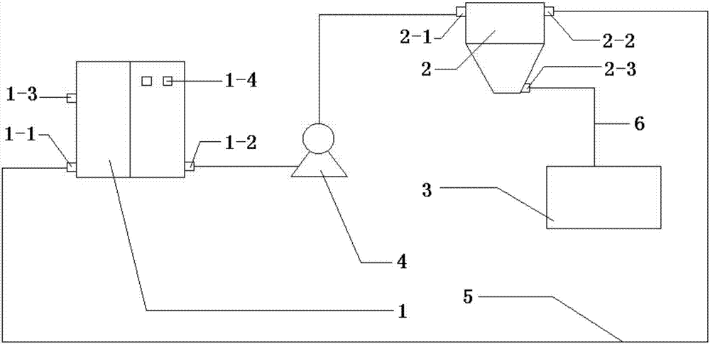
[0025] An anaerobic biological decalcification system, comprising an anaerobic reactor 1, a calcium salt separation tank 2, a calcium salt storage tank 3 and a pump 4, the anaerobic reactor 1 is provided with a sludge feed port 1-1, Sludge discharge port 1-2, sewage water inlet 1-3 and sewage water outlet 1-4, described calcium salt separation tank 2 is provided with calcium salt separation tank feed port 2-1, calcium salt separation tank sludge Discharge port 2-2 and calcium salt separation tank calcium salt discharge port 2-3, described sludge discharge port 1-2 is connected with calcium salt separation tank feed port 2-1 by pump 4, described The sludge discharge port 2-2 of the calcium salt separation tank is connected to the sludge feed port 1-1 through the sludge return pipe 5, and the calcium salt discharge port 2-3 of the calcium salt separation tank is connected to the calcium salt storage tank 3 connect.

[0026] In this embodiment, the calcium salt separation tank 2...

Embodiment 2

[0028] As described in Example 1, the difference is:

[0029] The calcium salt separation tank 2 is a vertical separation tank, and the height of the calcium salt separation tank 2 is 7m.

Embodiment 3

[0031] Utilize the system described in embodiment 1 to carry out the method for anaerobic biological decalcification, comprise steps as follows:

[0032] Open the anaerobic reactor 1, the sewage enters the anaerobic reactor 1 through the sewage water inlet 1-3, and controls the pH value of the anaerobic reactor 1 at 6.5-9 by adding sodium hydroxide or sodium bicarbonate when necessary, and the sewage Calcium ions in the anaerobic reactor are precipitated in the form of calcium salt and mixed in the anaerobic sludge in the anaerobic reactor 1, and then the anaerobic sludge in the anaerobic reactor 1 is passed through the pump 4 from the sludge outlet 1-2 Enter the calcium salt separation tank 2 through the feed port 2-1 of the calcium salt separation tank for precipitation. The calcium salt is heavier than the anaerobic sludge and will automatically precipitate to the bottom of the calcium salt separation tank 2. The precipitated calcium salt is separated from the calcium salt. ...


PUM

PropertyMeasurementUnit
heightaaaaaaaaaa

Abstract

The invention relates to an anaerobic biological decalcification system and method. The system comprises an anaerobic reactor, a calcium salt separation tank, a calcium salt storage tank and a pump, wherein a sludge feeding port, a sludge discharging port, a sewage inlet and a sewage outlet are formed in the anaerobic reactor; a calcium salt separation tank feeding port, a calcium salt separation tank sludge discharging port and a calcium salt separation tank calcium salt discharging port are formed in the calcium salt separation tank; the sludge discharging port is connected with the calcium salt separation tank feeding port through the pump; the calcium salt separation tank sludge discharging port is connected with the sludge feeding port through a sludge reflux pipe, and the calcium salt separation tank calcium salt discharging port is connected with the calcium salt storage tank. Calcium salt separation is realized in a natural separation manner, no complicated mechanical equipment is required, power consumption is saved, investments of system construction are reduced, operation is simple, and management and operation are convenient.

Description

technical field [0001] The invention relates to an anaerobic biological decalcification system and a decalcification method, belonging to the technical field of environmental protection water treatment and purification. Background technique [0002] In recent years, with the gradual implementation of national environmental protection policies, industrial enterprises have gradually strengthened their investment in the construction of sewage treatment systems. Compared with other countries in the world, the per capita water consumption in our country is relatively low, and the cost of industrial water use has increased year by year. High. In recent years, the country has also restricted the amount of clean water used per ton of product in some industries. In order to reduce the amount of clean water used per ton of product, some industries have increased the cycle of production water. Some enterprises have adopted measures to reuse water after sewage treatment to further reduce...

Claims


Application Information

Patent Timeline
Patent Type & Authority Applications(China)
IPC IPC(8): C02F3/28
CPCC02F3/28C02F1/66C02F2001/007
Inventor 彭吉成
Owner 山东环发科技开发有限公司
Why Eureka
Try Eureka