Full-rotating dynamic pointing type rotating guide system and guide controlling method

A rotary steerable and dynamic steerable technology, applied in the technical fields of directional drilling and rotary steerable drilling, can solve problems such as the strength of the drill string is not as good as that of the push-on type, the direction of the drill bit is deflected, and the build-up rate of hard formations is low. The effect of simple structure and accurate guiding direction

Active Publication Date: 2017-08-18
CHINA UNIV OF PETROLEUM (EAST CHINA)
View PDF6 Cites 5 Cited by
  • Summary
  • Abstract
  • Description
  • Claims
  • Application Information

AI Technical Summary

Problems solved by technology

Its disadvantages are: because the drive shaft of the drill bit needs to be bent, the position of the drive shaft is easy to wear, the strength of the drill string is not as good as that of the push-on type, and the inclination rate of the hard formation is low
However, the hybrid rotary steerable system still uses intermittent pulse force to achieve steering, and the drill bit will deflect during the time interval of the pulse force. On the other hand, whether the steering angle needs to be changed downhole, the push mechanism will provide lateral push force to deflect the direction of the drill bit

Method used


Image

  • Full-rotating dynamic pointing type rotating guide system and guide controlling method
  • Full-rotating dynamic pointing type rotating guide system and guide controlling method
  • Full-rotating dynamic pointing type rotating guide system and guide controlling method

Examples


Embodiment Construction

[0038] Below in conjunction with accompanying drawing and embodiment the present invention will be further described:

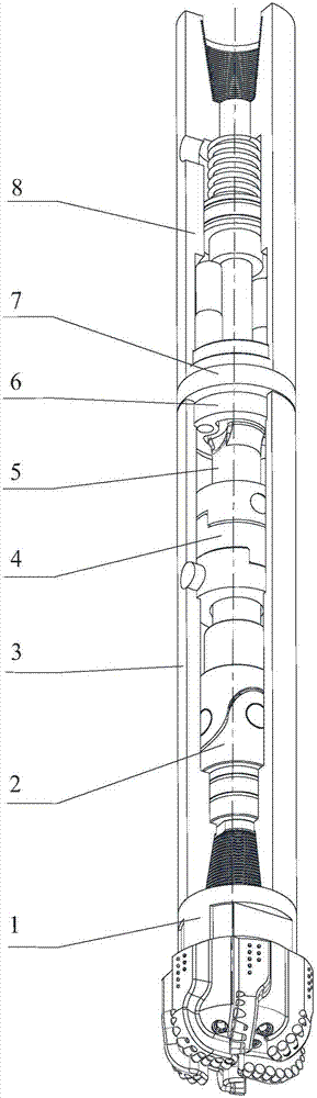
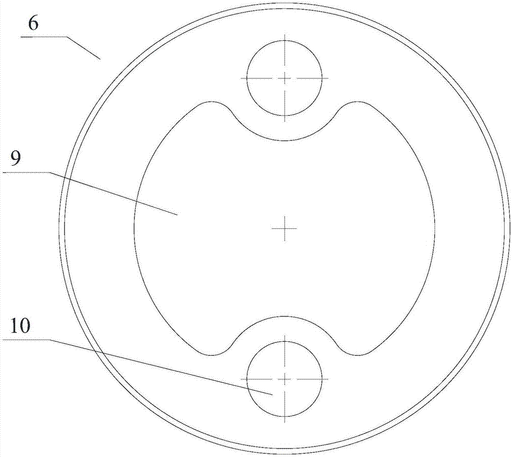
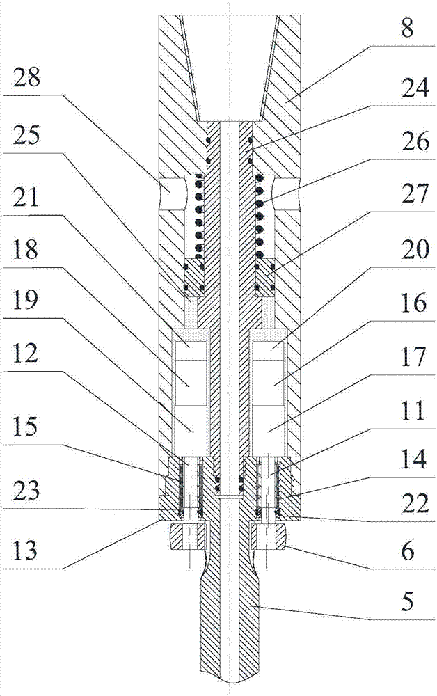
[0039] Such as figure 1 As shown, the full-rotation dynamic pointing type rotary steering system disclosed in the present invention includes a drill bit 1, a universal joint 2, a lower housing 3, a cross slider mechanism 4, a transmission shaft 5, a balance wheel 6, a guide drive mechanism 7, The upper casing 8; the drill bit 1 is fixedly connected with the lower casing 3; the lower casing 3 is fixedly and sealed connected with one end of the universal joint 2; the yaw wheel 6 is installed inside the lower casing 3 and the outer side of the drive shaft 5, and connected with the output end of the guide drive mechanism 7; the other end of the universal joint 2 is fixedly connected with the drive shaft 5; the drive shaft 5 is fixed and sealed with one end of the guide drive mechanism 7, or connected The drive mechanism 7 is integrated, and the other end of the ...


PUM


Abstract

The invention discloses a full-rotating dynamic pointing type rotating guide system and guide controlling method. The full-rotating dynamic pointing type rotating guide system comprises an upper shell body and a lower shell body. A hollow shaft coaxial with the upper shell body is arranged in the upper shell body, one end of the hollow shaft is connected with the upper shell body in a sealing mode, the other end of the hollow shaft is connected with a hollow transmission shaft, and a guide driving mechanism is arranged between the end of the hollow shaft and the upper shell body; the guide driving mechanism, the upper shell body and the hollow shaft form an oil pressure closed cavity, and the pressure of drilling liquid in the oil pressure closed cavity is higher than the pressure of drilling liquid outside the guide driving mechanism; the guide driving mechanism drives a deflection wheel mounted on the transmission shaft in a sleeving mode to conduct lateral deflection; a universal joint used for keeping the pointing direction is mounted on the transmission shaft; a drill is mounted at the end of the transmission shaft; and the deflection wheel conducts lateral deflection under driving of the guide driving mechanism and pushes the inner wall of the lower shell body outward and continuously in an abutting mode, and dynamic continuous lateral force with the direction being perpendicular to the inner wall of the lower shell body is produced, so that the lower shell body drives the drill to rotate by a certain angle along the rotating center of the universal joint to achieve the purpose of dynamic pointing.

Description

technical field [0001] The invention relates to advanced oil and gas drilling equipment technology, in particular to a rotary steerable drilling technology, which can be applied to directional drilling in different formations on sea and land. Background technique [0002] Rotary steerable drilling technology is a new drilling technology developed in the 1990s with rotary steerable drilling tools as the core. By controlling the wellbore trajectory in real time, it can accurately hit the drilling target. It has high mechanical penetration rate and high precision of wellbore trajectory control. The wellbore cleaning effect is good, and the displacement extension ability is strong, which is a qualitative leap from the traditional directional drilling technology. Rotary steerable drilling technology is becoming an important drilling method for various types of complex structure wells (horizontal wells, extended-reach wells, multilateral wells, 3D multi-target wells, and thin pay ...

Claims


Application Information

Patent Timeline
Patent Type & Authority Applications(China)
IPC IPC(8): E21B7/06
CPCE21B7/06
Inventor 武加锋王瑞和张锐秦冬黎
Owner CHINA UNIV OF PETROLEUM (EAST CHINA)
Why Eureka
Try Eureka