Control strategy for super capacitor energy storage system current transformer

A technology of supercapacitor and energy storage system, which is applied in current collectors, AC power input conversion to DC power output, electric vehicles, etc. It can solve problems such as deterioration of power supply quality, restrictions on wind power, photovoltaic access, etc., and achieves good results. Fast Track Effects

Active Publication Date: 2017-08-18
STATE GRID CORP OF CHINA +3
View PDF4 Cites 14 Cited by
  • Summary
  • Abstract
  • Description
  • Claims
  • Application Information

AI Technical Summary

Problems solved by technology

In the current power system, the proportion of new energy represented by wind power and photovoltaic is getting higher and higher, but due to its own

Method used


Image

  • Control strategy for super capacitor energy storage system current transformer
  • Control strategy for super capacitor energy storage system current transformer
  • Control strategy for super capacitor energy storage system current transformer

Examples


Embodiment Construction

[0043]The control strategy for the supercapacitor energy storage system converter of the present invention will be further described below using the drawings and embodiments.

[0044] The control strategy for the converter of the supercapacitor energy storage system of the present invention comprises the following steps:

[0045] 1) Analyze the energy distribution state of the supercapacitor energy storage system in different working modes

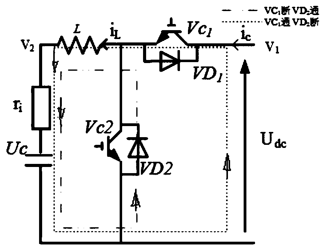
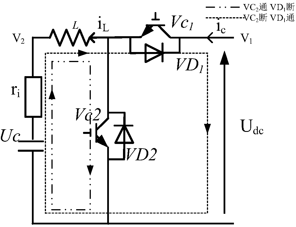
[0046] When the DC / DC converter works in step-down mode, such as figure 1 , at this time VC1 and VD2 are action switches. When the DC / DC converter works in boost mode, such as figure 2 , at this time VC2 and VD1 are action switches. VC1 and VC2 are pulse width modulation control switches.

[0047] 2) Establish a mathematical model of the system

[0048] Regardless of whether the circuit is in boost mode or buck mode, its mathematical model is similar, except that the direction of the current iL is different. Therefore, taking the bo...


PUM


Abstract

The invention relates to a control strategy for a super capacitor energy storage system current transformer. The control strategy is characterized by comprising steps of analyzing energy distribution states of a super capacitor energy storage system in different work modes, establishing a system mathematics model, designing a control strategy of a bidirectional DC/DC current transformer and designing a control strategy of a DC/AC voltage source type current transformer, the bidirectional DC/DC current transformer and the DC/AC voltage source type current transformer are taken as power adjusting devices, and power throughput of the super capacitor energy storage system and DC side voltage control are realized. A simulation system is established based on PSCAD/EMTDC software, accurate and rapid response to designated charging and discharging powers can be realized by the super capacitor energy storage system, DC side voltage work is stable, and work efficiency is high.

Description

technical field [0001] The invention relates to a control strategy for supercapacitor energy storage, which is a control strategy for a converter of a supercapacitor energy storage system, and is used to improve the output quality of distributed power sources represented by wind power and photovoltaics. Background technique [0002] With the depletion of fossil fuels and the increasingly severe problems of global warming, the development of renewable energy such as wind power and photovoltaics has received high attention. In the current power system, the proportion of new energy represented by wind power and photovoltaic is getting higher and higher. However, due to its own characteristics such as volatility and randomness, the quality of power supply deteriorates, thus limiting the access of wind power and photovoltaic. [0003] Energy storage system is regarded as one of the effective means to improve the smooth grid connection of distributed power generation because it ca...

Claims


Application Information

Patent Timeline
IPC IPC(8): H02M7/797H02J3/32H02J7/34
Inventor 李军徽葛延峰蒋莲严干贵李大路傅予
Owner STATE GRID CORP OF CHINA
Why Eureka
Try Eureka