Surgical membrane

An implant and cartilage technology, used in joint implants, joint implants, surgery, etc., can solve the problems of difficulty in repairing damage in joints, futility of surgery, etc., and achieve the effect of easy individualization

Active Publication Date: 2017-08-18
EPISURF IP MANAGEMENT
View PDF15 Cites 4 Cited by
  • Summary
  • Abstract
  • Description
  • Claims
  • Application Information

AI Technical Summary

Problems solved by technology

For the patient, even small displacements or deviations from the ideal position can result in pain, longer recovery periods, or even make surgery futile and more difficult to repair damage in the joint

Method used


Image

  • Surgical membrane
  • Surgical membrane
  • Surgical membrane

Examples


Embodiment Construction

[0081] introduce

[0082] The embodiments herein relate to a design method 2 for designing an individual custom implant 1 . The implant 1 designed by the method 2 according to the embodiments herein is used for cartilage repair in human or animal joints.

[0083] Design Method 2 for designing an individual custom implant according to embodiments herein is described below.

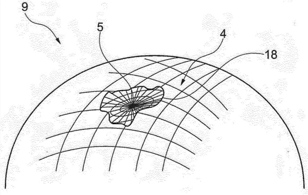
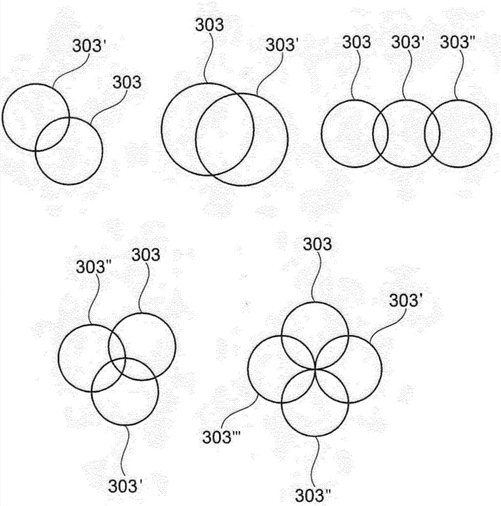
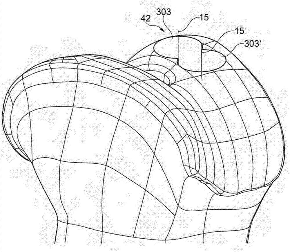
[0084]Embodiments herein relate to a design method for designing independently customized implants based on a 3D virtual model of the implant. The design method comprises identifying the lesion area, presenting a virtual 3D view of the identified area, forming a 3D virtual implant comprising a shape virtually arranged in the 3D view, wherein the shaped area covers or partially covers the identified lesion area, An implant is fabricated from the formed 3D virtual implant.

[0085] The design method 2 for designing an independently customized implant 1 according to the embodiments here is a 3D computer p...


PUM


Abstract

A reinforced surgical membrane for supporting bone growth by shielding a bone cavity from soft tissue ingrowth comprises are a reinforcing layer (2) between a first membrane layer and a second membrane layer (4). The reinforcing layer (2) has defined therein an array of holes (3) which may connect the first and second membrane layers.

Description

technical field [0001] The present invention relates generally to the field of orthopedic surgery, and to cartilage and or bone surface repair. Embodiments herein relate to implants for replacing a portion of cartilage and / or a portion of bone, and to design methods for such implants. Further embodiments also relate to surgical kits, tool kits, and methods for replacing a portion of an articular surface of a joint. Background technique [0002] In surgical procedures where small implants are placed, setting the implant in a precise manner is critical. If the implant misaligns from its intended position, this can cause increased wear or load on the joint. For example, if the implant tilts, it can cause the edges to protrude above the cartilage tissue and cause wear on the opposing cartilage of the joint. Another example is when an implant is placed with the surface of the implant protruding above the surface of the cartilage, this will cause the joint to move in an uneven ...

Claims


Application Information

Patent Timeline
Patent Type & Authority Applications(China)
IPC IPC(8): A61F2/30
CPCA61F2/30756A61F2/30942A61F2002/3013A61F2002/30878A61F2002/30897A61F2002/30948A61F2002/30952A61B17/00A61F2/38
Inventor N.贝克R.利利斯特拉尔M.奥特罗奎维多
Owner EPISURF IP MANAGEMENT
Why Eureka
Try Eureka