Smelting system for alloy

A technology of alloy and smelting furnace, which is applied in the field of smelting system for alloys, can solve the problem of uncontrollable cooling rate and achieve the effect of cost saving

Active Publication Date: 2017-08-22
洛阳八佳电气科技股份有限公司
View PDF6 Cites 4 Cited by
  • Summary
  • Abstract
  • Description
  • Claims
  • Application Information

AI Technical Summary

Problems solved by technology

[0003] The purpose of the present invention is to provide a smelting system for alloys in order to solve the problem that the cooling rate is uncontrollable during the cooling process after alloy smelting

Method used


Image

  • Smelting system for alloy
  • Smelting system for alloy
  • Smelting system for alloy

Examples


Embodiment Construction

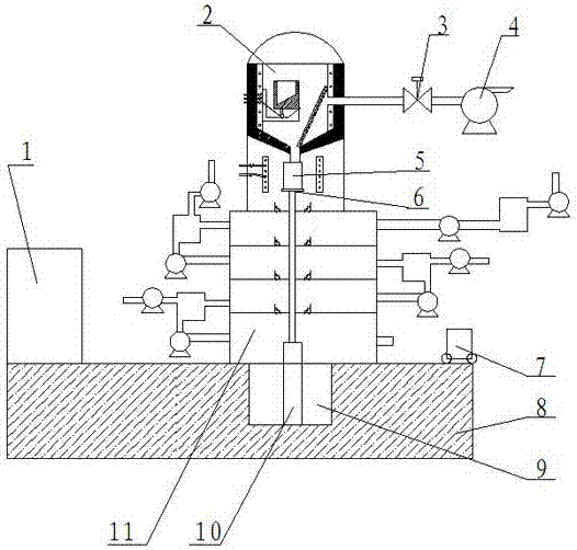
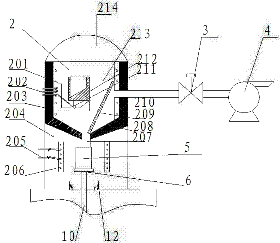
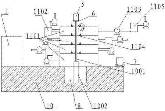
[0032] As shown in the figure, the specific implementation method is as follows:

[0033] A smelting system for alloys, comprising a smelting furnace 2, a cooling furnace 11 and a base 8 arranged sequentially from top to bottom, an upper cover 214 is set on the top of the smelting furnace, and a control system 1 for controlling the operation of the entire system is set on the base 8 The smelting furnace 2 includes a smelting cavity and a heat preservation cavity arranged in sequence from top to bottom. The smelting furnace 2 is connected with a vacuum system 4 that provides a vacuum smelting environment for the smelting cavity and an intake and exhaust solenoid valve 3 that controls the opening and closing of the vacuum system. A mold 5 for cooling and forming the alloy is also provided in the heat preservation chamber of the furnace 2, and a channel connecting the heat preservation chamber of the smelting furnace 2 and the cooling furnace 11 is provided directly below the mold...


PUM


Abstract

A smelting system for an alloy comprises a smelting furnace, a cooling furnace and a base, all of which are sequentially arranged from top to bottom. The base is provided with a control system controlling work of the whole system. A cooling furnace cavity is internally divided into a plurality of air flues from top to bottom in sequence. The air flues, from top to bottom, in the furnace cavity are mutually matched to form a die cooling zone. The air flue temperature in the cooling zone is gradually reduced. The air flues are inflated with constant-temperature air through a constant-temperature air supply system. The temperature of the constant-temperature air is controlled so as to control the cooling rate of the die when the constant-temperature air exchanges heat with a metal solution in the die. The cooling furnace is arranged below the smelting furnace, the die is controlled to enter the cooling furnace through a hydraulic cylinder, and die transferring is avoided; meanwhile, the different air flues are arranged in the cooling furnace, the die is subjected to staged cooling in the different air flues, and accordingly the cooling rate is controlled.

Description

technical field [0001] The invention relates to a smelting device, in particular to a smelting system for alloys. Background technique [0002] As is known, the preparation process of metal alloy materials is to add various other required metal materials in proportion and time during the smelting process of the base material, and then take them out after pouring them into the fixed abrasive mold after naturally cooling down to room temperature. The required alloy material is obtained by machining; during the cooling process, due to the uncontrollable cooling rate, the metallographic structure of the alloy material is arranged irregularly, and the material properties of the final product are unstable. Contents of the invention [0003] The object of the present invention is to provide a smelting system for alloys in order to solve the problem of uncontrollable cooling rate in the cooling process after alloy smelting. [0004] The present invention is for solving the defici...

Claims


Application Information

Patent Timeline
Patent Type & Authority Applications(China)
IPC IPC(8): C22C1/02B22D27/04
CPCB22D27/04C22C1/02
Inventor 王宇
Owner 洛阳八佳电气科技股份有限公司
Why Eureka
Try Eureka