
Memory Cell Distortion Measurement Method

A storage unit and measurement method technology, applied in measurement devices, static memories, instruments, etc., can solve problems such as inability to guarantee accuracy, and achieve the effects of improving flexibility, reasonable parameter selection, and high efficiency

Active Publication Date: 2019-06-28
WUHAN XINXIN SEMICON MFG CO LTD
View PDF11 Cites 0 Cited by
  • Summary
  • Abstract
  • Description
  • Claims
  • Application Information

AI Technical Summary

Problems solved by technology

[0004] The object of the present invention is to provide a storage unit distortion measurement method to solve the problem that the existing storage unit distortion measurement method cannot guarantee the accuracy

Method used


Image

  • Memory Cell Distortion Measurement Method
  • Memory Cell Distortion Measurement Method
  • Memory Cell Distortion Measurement Method

Examples


Embodiment 1

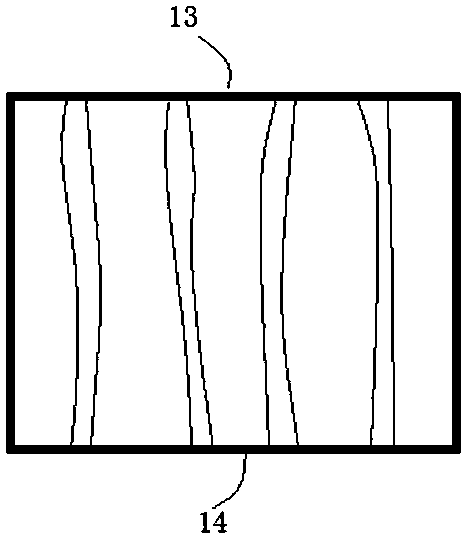
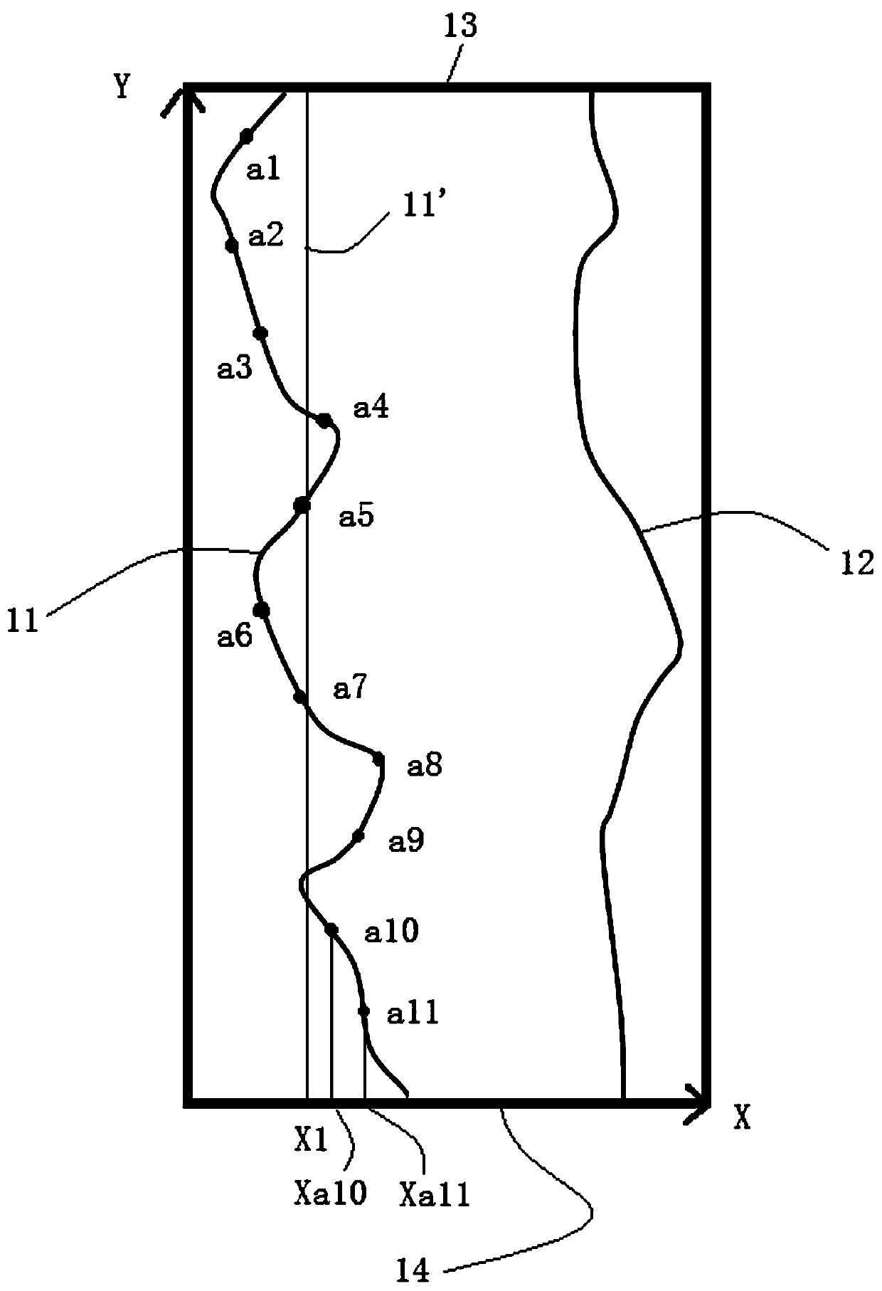
[0060] Such as figure 1 As shown, the number of the storage unit is single, and the storage unit also includes an upper boundary 13 and a lower boundary 14, wherein: the shortest distance from the upper boundary 13 to the lower boundary 14 is in the vertical direction. In addition, storage units have another structural relationship, such as figure 2 As shown, there are multiple storage units, and multiple storage units are arranged in a storage device, and the storage device is a three-dimensional non-volatile storage device, wherein: the storage device includes an upper boundary 13 and lower bound 14, as in image 3 As shown, the shortest distance from the upper boundary 13 to the lower boundary 14 is the vertical direction, that is, the direction of the coordinate axis Y; one or more storage units are arranged along the vertical direction, image 3 Only the memory device section is listed, and only one memory cell is shown.

[0061] A storage unit distortion measurement...

Embodiment 2

[0077] Such as Figure 5 As shown, this embodiment also provides a storage unit distortion measurement method, the storage unit distortion measurement method includes: determining the center line 15 of the storage unit; determining the center reference line 15' of the storage unit; calculating the The variance of the central line 15 and the central reference line 15' is proportional to the degree of distortion of the storage unit.

[0078] Specifically, the determination of the centerline 15 of the storage unit includes: selecting a plurality of left centerline collection points on the left boundary 11, preferably, the left reference line collection point when determining the left reference line 11' can be used a1-a11; similarly, select a plurality of collection points of the right center line on the right boundary 12, and can adopt the collection points b1-b11 of the right reference line when determining the right reference line 12'; multiple collection points of the left cen...


PUM


Abstract

The present invention provides a storage unit distortion measurement method, the storage unit distortion measurement method comprising: determining the left boundary and the left reference line of the storage unit, and / or determining the right boundary and the right reference line of the storage unit; Calculate the variance of the left boundary and the left reference line, and / or calculate the variance of the right boundary and the right reference line; wherein, the variance is proportional to the degree of distortion of the storage unit. The storage unit distortion measurement method in the present invention uses one or more variance values ​​to measure the value of the storage unit distortion degree, which can be realized only by using an ordinary scanning device and a calculation unit, which overcomes the manual measurement in the prior art The problems of low precision, large error and cumbersome operation.

Description

technical field [0001] The invention relates to the technical field of semiconductors, in particular to a storage unit twist measurement method. Background technique [0002] In a three-dimensional non-volatile memory device, including one or more storage units, the degree of distortion of the storage unit is a very critical parameter. If the storage unit has a large degree of distortion, and the accuracy of the measuring instrument is not Reasonable, the distortion of the storage unit will not be properly processed in the entire manufacturing process of the storage device, which will not only make the measurement of the key dimensions of the storage device inaccurate and difficult to control, but also cause errors in the connection relationship between some storage units. The entire memory device fails. The distortion measurement of the existing storage unit is performed manually by using traditional measuring instruments, the efficiency is very low, and the accuracy canno...

Claims


Application Information

Patent Timeline
Patent Type & Authority Patents(China)
IPC IPC(8): G01B21/20G11C29/56
CPCG01B21/20G11C29/56
Inventor 刘磊陆磊周第廷
Owner WUHAN XINXIN SEMICON MFG CO LTD
Learn More