
High-gain antipodal Vivaldi antenna

A high-gain, antenna technology, applied in the field of antennas, can solve problems such as inoperability, increased electrical length, and small antenna gain, and achieves the effects of low cost, convenient processing, and simple and reliable structure

Active Publication Date: 2017-08-22
UNIV OF ELECTRONIC SCI & TECH OF CHINA
View PDF5 Cites 5 Cited by
  • Summary
  • Abstract
  • Description
  • Claims
  • Application Information

AI Technical Summary

Problems solved by technology

[0008] The third is that the researcher R. Natarajan increases the electrical length by opening a defect structure on the radiation patch of the antenna, so that the volume of the antenna is reduced while ensuring the working bandwidth of the antenna, but its gain is small. See the literature " R.Natarajan, J.V.George, M.Kanagasabai, and A.K.Shrivastav, "A Compact AntipodalVivaldi Antenna for UWB Applications," Antennas and Wireless Propagation Letters, IEEE, Volume: 14, 2015";
[0009] Among the above three methods, the working frequency band of the antenna realized by the first method is 2-32GHz, the working frequency band of the antenna realized by the second method is 1-35GHz, and the working frequency band of the antenna realized by the third method is 3.7-18GHz; Although the gain of the first type of antenna has been greatly improved, there is still a lot of room for improvement in the performance of the high frequency band; although the second type of antenna has widened the bandwidth of the antenna, it still cannot work in the Ka band and above frequency bands, and its gain is also small ;The gain of the third antenna is small (less than 7dBi), and it cannot work in a higher frequency band; so these three antennas have their own limitations

Method used


Image

  • High-gain antipodal Vivaldi antenna
  • High-gain antipodal Vivaldi antenna
  • High-gain antipodal Vivaldi antenna

Examples


Embodiment Construction

[0040] The present invention will be described in further detail below in conjunction with the accompanying drawings and embodiments.

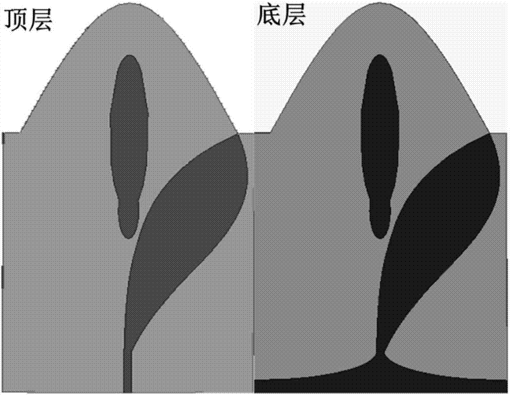
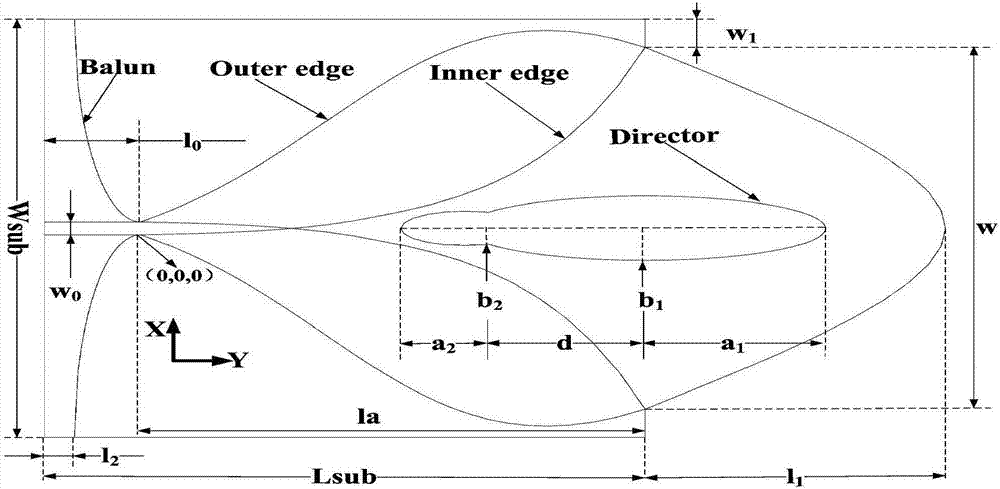
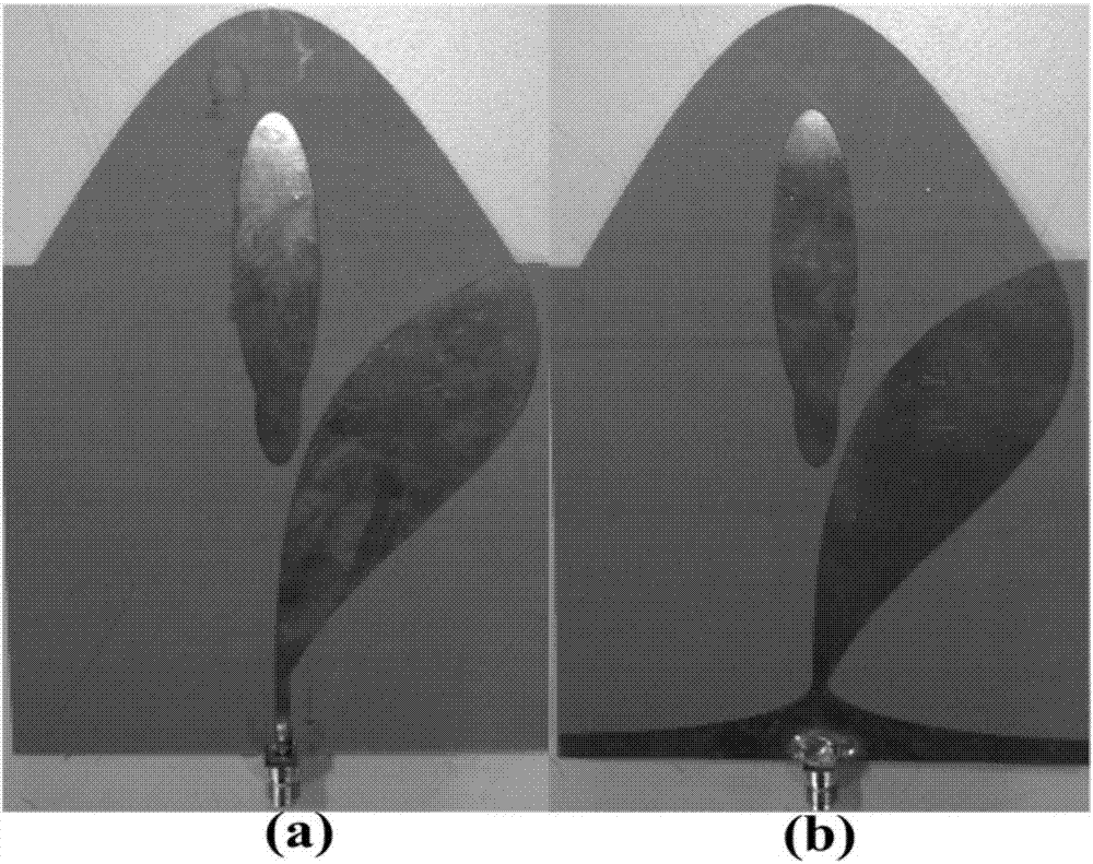
[0041] In this embodiment, a high-gain pair extension Vivaldi antenna is provided, and its structure is as follows figure 1 As shown, the processed objects are as image 3 As shown, the dual extension Vivaldi antenna is implemented on the dielectric substrate of RT / Duroid 5880. The relative permittivity of the substrate is 2.2, the loss tangent is 0.0009, and the thickness is 0.787mm. Its specific parameters are as figure 2As shown, specifically:

[0042] Wsub Lsub w 0

l 0

w 1

l 1

96.52mm 100mm 3mm 16mm 6.26mm 50mm a 1

a 2

b 1

b 2

d l 2

30mm 10mm 7.5mm 4mm 24mm 5mm s c pa pb h 40mm 2 0.065 0.05 0.787mm

[0043] The above-mentioned high-gain pair extension Vivaldi antenna is tested, and the results are as follows Figure 4 to Figur...


PUM


Abstract

The invention belongs to the field of antennas, and provides a high-gain antipodal Vivaldi antenna. The high-gain antipodal Vivaldi antenna comprises a dielectric substrate, a balance feed Balun, an upper-layer radiation patch and a lower-layer radiation patch, wherein an antenna radiation aperture is further provided with a director, and the director is composed of two composite metal patches which are positioned on the upper and lower surfaces of the dielectric substrates and arranged in a correspondingly overlapped manner; and each composite metal patch is formed by intersecting a small oval metal patch and a large oval metal patch, the small oval metal patch is close to the antenna radiation aperture, and the large oval metal patch is away from the antenna radiation aperture. The high-gain antipodal Vivaldi antenna introduces the director at the antenna radiation aperture on the basis of a traditional antipodal Vivaldi antenna, and replaces exponential curves of internal flanges of the upper-layer radiation patch and the lower-layer radiation patch with composite exponential curves, thereby realizing the purpose of expanding antenna bandwidth and improving antenna gain and directionality.

Description

technical field [0001] The invention belongs to the field of antennas, relates to broadband antennas, and specifically provides an antipodal Vivaldi antenna (Antipodal Vivaldi Antenna, AVA) based on a director and a novel composite exponential curve, so as to expand the bandwidth of the antenna and improve the gain and directivity of the antenna. Purpose. [0002] technical background [0003] The antenna is an essential part of various radio equipment, it can effectively radiate or receive radio waves and connect with the transceiver system through the feeder, and play the role of energy conversion. As the front-end component of the communication system, the antenna is called the "eye" in the communication system, which largely restricts the development of the entire communication technology. The bandwidth, gain and directivity of the antenna are very important indicators. Researchers hope to achieve the highest possible gain and good directivity under the premise of ensuri...

Claims


Application Information

Patent Timeline
IPC IPC(8): H01Q1/36H01Q1/38H01Q1/50
CPCH01Q1/36H01Q1/38H01Q1/50
Inventor 刘宇倪明环夏鑫淋周鹏杨涛杨自强
Owner UNIV OF ELECTRONIC SCI & TECH OF CHINA
Features
  • Generate Ideas
  • Intellectual Property
  • Life Sciences
  • Materials
  • Tech Scout
  • Unparalleled Data Quality
  • Higher Quality Content
  • 60% Fewer Hallucinations
Learn More