
Intelligent relay test protection device based on Internet of things

An intelligent, Internet of Things technology, applied in emergency protection circuit devices, electrical components, circuit devices, etc., can solve the problems of tight land use, potential safety hazards, and reduced heat dissipation performance at the use site, reducing land use requirements and improving practicability. , to achieve the effect of cooling effect

Inactive Publication Date: 2017-08-22
SHAANXI BROADCAST & TV NETWORK INTERMEDIARY GRP CO LTD
View PDF2 Cites 6 Cited by
  • Summary
  • Abstract
  • Description
  • Claims
  • Application Information

AI Technical Summary

Problems solved by technology

[0003] During the use of the relay test and protection instrument, the internal circuit components are in a state of heating. In order to facilitate heat dissipation and cooling, there are usually heat dissipation ports on the bottom and top of the tester, and in order to achieve a good heat dissipation effect, it is usually necessary to open the support The feet make the equipment tilted, but this will easily cause two problems. First, although the simple heat dissipation vent can achieve heat dissipation and cooling effect through ventilation, the external dust can easily enter the interior of the equipment. When there is a lot of dust entering, It will also cause a decline in heat dissipation performance, and it will also cause safety hazards. Second, there are usually other test equipment at the use site. The land area is limited. When other instruments and equipment cannot be placed on the top of the test protector, it will easily lead to a shortage of land at the use site.

Method used


Image

  • Intelligent relay test protection device based on Internet of things
  • Intelligent relay test protection device based on Internet of things
  • Intelligent relay test protection device based on Internet of things

Examples


Embodiment Construction

[0031] The present invention is described in further detail now in conjunction with accompanying drawing. These drawings are all simplified schematic diagrams, which only illustrate the basic structure of the present invention in a schematic manner, so they only show the configurations related to the present invention.

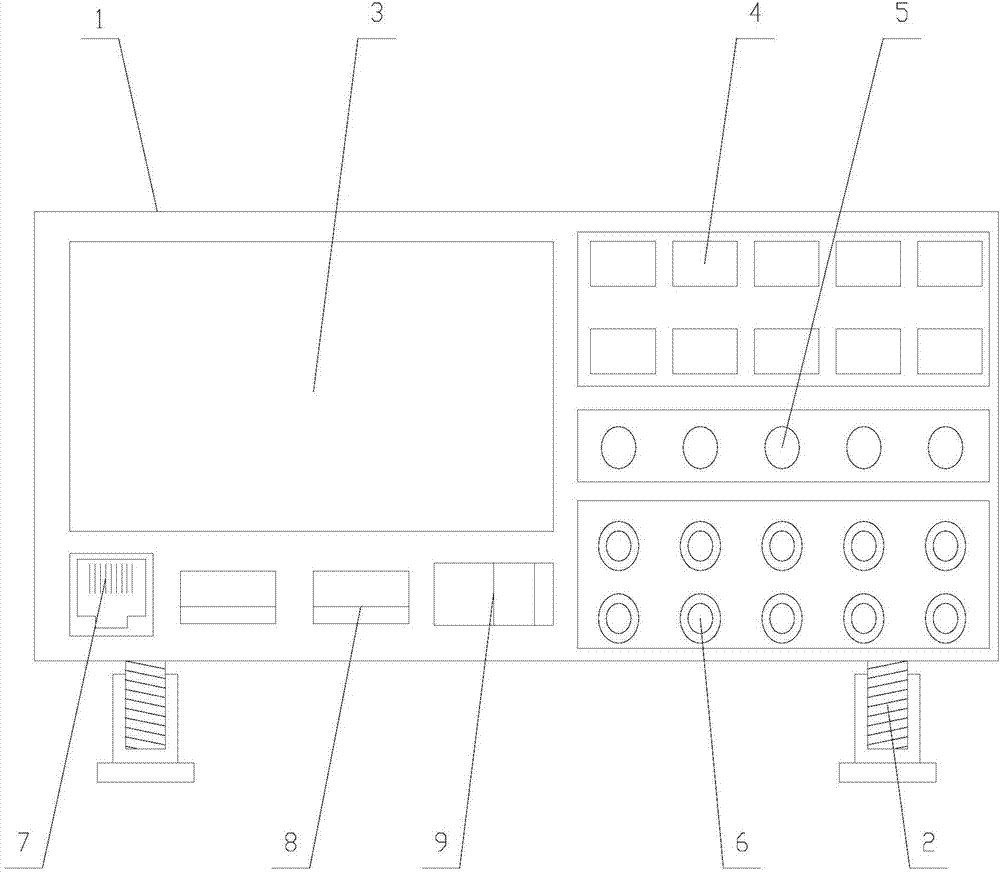
[0032] Such as Figure 1-Figure 8 As shown, an intelligent relay test protection instrument based on the Internet of Things includes a main body 1 and several support units 2 arranged under the main body 1. The front of the main body 1 is provided with a display screen 3, a switch 9, and several control buttons 4. A number of indicator lights 5, a number of signal line interfaces 6 and a number of USB interfaces 8, the back of the main body 1 is provided with a backplane lifting mechanism;

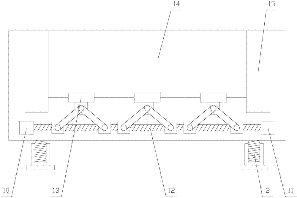
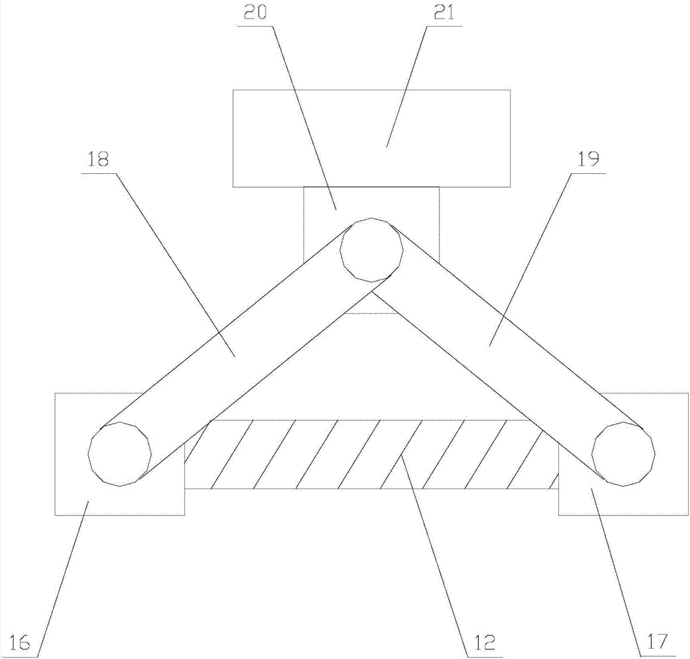
[0033] The backboard lifting mechanism includes a driving unit, a backboard 14 and several driven units 13, the driving unit is connected to the backboard 14 through the ...


PUM


Abstract

The invention relates to an intelligent relay test protection device based on the Internet of things. The intelligent relay test protection device comprises a main body, wherein the back surface of the main body is provided with a back plate lifting mechanism, the back plate lifting mechanism comprises a driving unit, a back plate and a plurality of driven units, each driven unit comprises a first moving block, a second moving block, a first connecting rod, a second connecting rod, a lifting block and a supporting block, a cooling mechanism is arranged in the main body, the cooling mechanism comprises a transmission mechanism, a cooling unit and a sliding unit, and the cooling unit comprises a first air pipe, an air pump, a fixed block, a second air pipe, a cooling pipe, a third air pipe and a cooling spray nozzle. According to the intelligent relay test protection device based on Internet of things, other instruments and equipment can be placed on the top part of the main body conveniently through lifting the back plate by means of the back plate lifting mechanism, the space occupation requirement is reduced, furthermore, the temperature is reduced through driving the cooling unit to move back and forth by means of the transmission mechanism, such that the cooling effect is achieved while preventing external dust from entering into the main body to affect equipment operation, thereby enhancing the practicality of the equipment.

Description

technical field [0001] The invention relates to the field of electric equipment, in particular to an intelligent relay test protection instrument based on the Internet of Things. Background technique [0002] The relay test protection instrument is based on the "Technical Conditions for Microcomputer Relay Protection Test Device (Discussion Draft)" issued by the Ministry of Electric Power, extensively listens to user opinions, summarizes the advantages and disadvantages of similar domestic products, and fully uses modern and advanced A new miniaturized microcomputer relay test protection realized by microelectronic technology and devices. When the power components in the power system (such as generators, lines, etc.) or the power system itself fail to endanger the safe operation of the power system, it can send a warning signal to the operator on duty in time, or directly send a trip command to the controlled circuit breaker To terminate the development of these events, so ...

Claims


Application Information

Patent Timeline
IPC IPC(8): H02H1/00H02B1/26H02B1/56
CPCH02B1/26H02B1/565H02H1/00
Inventor 曹燕红
Owner SHAANXI BROADCAST & TV NETWORK INTERMEDIARY GRP CO LTD
Learn More