Regional voltage layered and distributed cooperative control system of photovoltaic power distribution network

A technology of voltage control and distributed coordination, applied in photovoltaic power generation, AC network voltage adjustment, electrical components, etc., can solve problems such as high cost of installation and maintenance of energy storage devices, long decision-making time, and large amount of measurement data

Active Publication Date: 2017-08-22
NINGBO POWER SUPPLY COMPANY STATE GRID ZHEJIANG ELECTRIC POWER +1
View PDF1 Cites 24 Cited by
  • Summary
  • Abstract
  • Description
  • Claims
  • Application Information

AI Technical Summary

Problems solved by technology

One is centralized control, aiming at global optimization of the system and uniformly deploying controllable resources, but there are many shortcomings: large amount of measurement data, long decision-making time, heavy communication burden and high investment cost
However, when the distributed control strategy is used to control photovoltaics for reactive power compensation and active power reduction, the voltage quality is often taken as the control target, and the consideration of voltage regulation costs is ignored
[0005] At the same time, the distributed or centralized control strategy controls the energy storage device to charge when the distributed photovoltaic power is too high, and to discharge when the load is maximum, which can effectively ensure the power supply quality of the distribution network, but the cost of installing and maintaining the energy storage device is high. It will also increase the difficulty of controlling
[0006] In summary, the existing photovoltaic distribution network voltage control strategy has a high cost of voltage regulation

Method used


Image

  • Regional voltage layered and distributed cooperative control system of photovoltaic power distribution network
  • Regional voltage layered and distributed cooperative control system of photovoltaic power distribution network
  • Regional voltage layered and distributed cooperative control system of photovoltaic power distribution network

Examples


Embodiment Construction

[0048] The technical solutions in the embodiments of the present invention will be clearly and completely described below in conjunction with the accompanying drawings in the embodiments of the present invention. Obviously, the described embodiments are only some of the embodiments of the present invention, not all of them. Based on the embodiments of the present invention, all other embodiments obtained by persons of ordinary skill in the art without creative work all belong to the protection scope of the present invention.

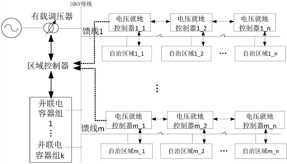
[0049] The distribution network structure diagram and regional voltage layered collaborative control framework applied in this embodiment are as follows: figure 1 shown. The distribution network includes 110 / 10kV substations, multiple 10kV feeders and many 10kV users. Some of the 10kV users are equipped with photovoltaic power generation systems, and each is regarded as an autonomous area, equipped with a local voltage controller. The on-load tap chang...


PUM


Abstract

The invention provides a regional voltage layered and distributed cooperative control system of a photovoltaic power distribution network. When voltage does not exceed the limit on a user layer, local reactive compensation will come into play so as to restrain generation of overvoltage. When feeder line voltage exceeds the limit, the passive compensation of distributed cooperative control comes into play in advance so as to reduce voltage regulation cost. When passive capacity is completely consumed and the voltage still exceeds the limit, an active shrinkage strategy of the distributed cooperative control acquires an optimized photovoltaic active shrinkage solution through little distribution communication and local calculation. When feeder line voltage recovers to normal, through the power recovery control, maximized photovoltaic power generation benefits can be ensured. Through transformer station layer voltage, voltage information and in-station information based on feeder line key nodes are controlled, and by use of a nine-area graph of a fuzzy passive boundary, a limit exceeding problem of the feeder line voltage is solved by adjusting voltage of the low-voltage side of a transformer.

Description

technical field [0001] The present invention relates to the field of voltage control, more specifically, to a regional voltage layered distributed collaborative control system for photovoltaic distribution networks Background technique [0002] The ever-increasing energy demand and increasingly severe environmental problems have promoted the large-scale development and application of photovoltaic power generation technology. However, as the penetration rate of distributed photovoltaics increases, the operation and control of the power system is facing many challenges, among which the problem of voltage control is particularly prominent. [0003] The control objects of the distribution network voltage control strategy are divided into three categories: (1) traditional reactive voltage control equipment, such as capacitors, on-load tap changers (OLTC), etc.; (2) enhanced equipment, such as energy storage devices, Distribution static var compensator (DSTATCOM); (3) Distributed...

Claims


Application Information

Patent Timeline
Patent Type & Authority Applications(China)
IPC IPC(8): H02J3/12H02J3/38
CPCH02J3/12H02J3/383H02J2203/20Y02E10/56
Inventor 周开河朱承治徐孝忠龚向阳王威王波虞殷树方云辉贺旭王晴
Owner NINGBO POWER SUPPLY COMPANY STATE GRID ZHEJIANG ELECTRIC POWER
Why Eureka
Try Eureka