Pipeline connecting system with turbine and boiler arranged compactly

A technology for connecting systems and piping systems, applied in the field of power generation, can solve the problems of little change in unit operation economy, high price, small bending radius, etc., and achieve the effect of reducing usage, reducing pressure loss and heat dissipation loss, and saving investment.

Pending Publication Date: 2017-08-25
冯煜珵
View PDF1 Cites 9 Cited by
  • Summary
  • Abstract
  • Description
  • Claims
  • Application Information

AI Technical Summary

Problems solved by technology

Obviously, this conventional piping system connection method fails to take advantage of the high-level and low-level layout. Compared with the conventional steam turbine generator set layout, although it can greatly reduce the straight pipes of high-temperature and high-pressure steam pipelines, the elbows of the system There will still be more, because the resistance coefficient of the elbow is much larger than that of the straight pipe, if the cast steel elbow is used, not only the

Method used


Image

  • Pipeline connecting system with turbine and boiler arranged compactly
  • Pipeline connecting system with turbine and boiler arranged compactly
  • Pipeline connecting system with turbine and boiler arranged compactly

Examples


Embodiment 1

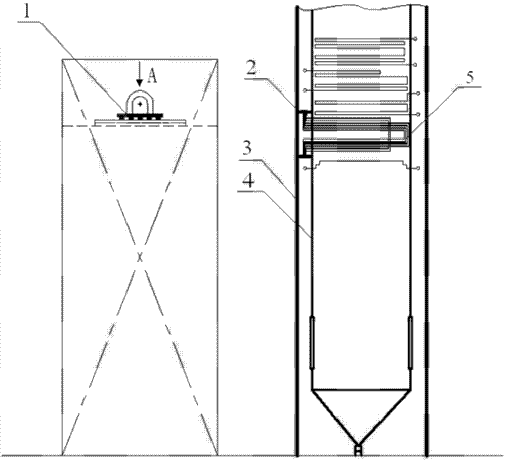
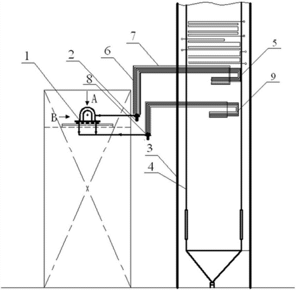
[0028] Such as image 3 As shown, it is a schematic diagram of a specific embodiment 1 of a pipeline connection system with a compact layout of a machine furnace of the present invention. Among them, the boiler adopts a tower furnace, and the high-level steam turbine is arranged in parallel with the boiler (viewed from the right side of the furnace to the left side of the furnace).

[0029] This embodiment mainly includes the final reheater 5, the final superheater 9, the final reheater outlet header 2, the final superheater outlet header 8, the high-level steam turbine 1 and the outlet header connected to the final reheater 2. The piping system between the outlet header 8 of the final superheater and the upper steam turbine 1.

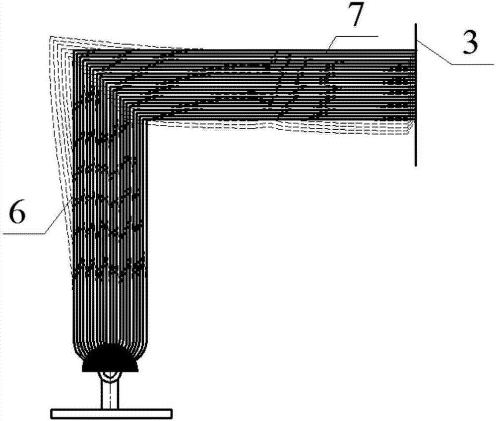
[0030] Among them, the outlet header 2 of the final reheater and the outlet header 8 of the final superheater are all attached to the high-level steam turbine 1, and the tube bundle arrangement between the outlet header 2 of the final reheater and th...

Embodiment 2

[0034] Such as Figure 4 As shown, it is a schematic diagram of a specific embodiment 2 of a pipeline connection system with a compact layout of a machine furnace of the present invention. Among them, the boiler adopts a tower furnace, and the high-level steam turbine and boiler (viewed from the right side of the furnace to the left side of the furnace) are arranged vertically in the horizontal direction.

[0035] This embodiment mainly includes the final reheater 5, the final superheater 9, the final reheater outlet header 2, the final superheater outlet header 8, the high-level steam turbine 1 and the outlet header connected to the final reheater 2. The piping system between the outlet header 8 of the final superheater and the upper steam turbine 1.

[0036] Among them, the outlet header 2 of the final reheater and the outlet header 8 of the final superheater are all attached to the high-level steam turbine 1, and the tube bundle arrangement between the outlet header 2 of t...

Embodiment 3

[0040] Such as Figure 5 Shown is a schematic diagram of a specific embodiment 3 of a pipeline connection system with a compact layout of a machine furnace according to the present invention. Taking the double reheat unit as an example, the boiler is a tower boiler, and the high-level steam turbine is arranged in parallel with the boiler (viewed from the right to the left of the furnace). It mainly includes the final superheater 9, the final primary reheater 5', the final superheater outlet header 8, last-stage primary reheater outlet header 12, high-level steam turbine 1, the main steam pipeline system between the last-stage superheater outlet header 8 and high-pressure cylinder 10 of high-level steam turbine 1, and the end The primary reheat steam piping system between the outlet header 5' of the primary reheater and the medium-pressure cylinder 11 of the high-level steam turbine 1.

[0041] Wherein, the outlet header 12 of the last-stage primary reheater is close to the up...


PUM


Abstract

The invention discloses a pipeline connecting system with a turbine and a boiler arranged compactly. The pipeline connecting system at least comprises a boiler with a boiler heating face and boiler outlet headers, the high-position turbine and pipeline systems connected between the boiler outlet headers and the high-position turbine. The boiler outlet headers are close to the high-position turbine, a boiler heating face pipe bundle (a heating face pipe bundle boiler outer section) connected with each boiler outlet header is arranged to be in an L shape comprising a horizontal section and a perpendicular section. Heat expansion and heat stress of the systems, between the boiler and the turbine, of the boiler outlet headers are absorbed through pipe bundles connected to the boiler outlet headers, short-distance connection of high-temperature and high-pressure steam pipelines between the turbine and the boiler can be achieved, the use amount of high-temperature and high-pressure pipeline materials, bends and other pipe fittings is substantively reduced, pressure losses and heat dissipation losses of the high-temperature and high-pressure steam pipeline systems are reduced in a real sense, finally, the investment of the pipeline systems is saved, and economical efficiency of a unit is improved as well.

Description

technical field [0001] The invention relates to a pipe connection system with a compact layout of a furnace, which belongs to the field of power generation. Background technique [0002] With the continuous improvement of material technology and the improvement of thermal power theory, the parameters of steam have experienced the development process of low pressure, medium pressure, high pressure, ultrahigh pressure, subcritical, supercritical and ultra supercritical. In order to further improve the efficiency of thermal power generation units, all countries in the world have successively developed units with higher parameters. However, to develop high-parameter units, the price of related materials will also increase significantly, especially for high-temperature and high-pressure steam pipes between machine furnaces, such as main steam pipes, reheat steam pipes, etc. If the parameters are raised from the current 600°C level to 700°C grade, calculated according to the curr...

Claims


Application Information

Patent Timeline
IPC IPC(8): F01K11/02
CPCF01K11/02F22B21/40F22B37/22F01K13/006
Inventor 冯煜珵
Owner 冯煜珵
Why Eureka
Try Eureka