
Cement kiln head high-temperature high-pressure waste heat boiler

A waste heat boiler, high temperature and high pressure technology, applied in cement production, furnace, waste heat treatment, etc., can solve problems such as poor safety, large water capacity, complex system, etc., and achieve the effect of improving efficiency

Inactive Publication Date: 2017-08-25
北京鑫泽清源植物秸秆技术有限公司
View PDF0 Cites 2 Cited by
  • Summary
  • Abstract
  • Description
  • Claims
  • Application Information

AI Technical Summary

Problems solved by technology

[0006] What is more serious is that the kiln head steam drum type low-temperature and low-pressure waste heat boiler has low thermal parameters and low thermoelectric efficiency, large water capacity and poor safety, complex system and large steel consumption, and high overall project cost
[0007] The waste heat and heat source of the cement kiln head is cement clinker, and its firing temperature is above 1300°C. The current cement cooler adopts the traditional air cooling process, which has serious energy waste. The only high-temperature hot air is used to support the combustion of cement. The hot air for heat exchange of the waste heat boiler at the kiln head is only 400°C

Method used


Image

  • Cement kiln head high-temperature high-pressure waste heat boiler
  • Cement kiln head high-temperature high-pressure waste heat boiler

Examples


Embodiment Construction

[0025] Combine below figure 2 The present invention is further analyzed.

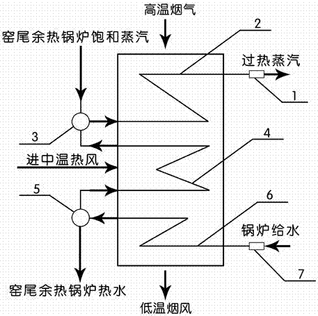
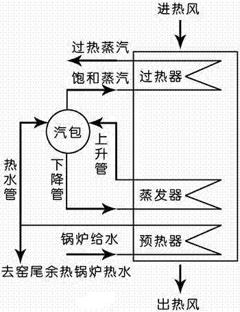
[0026] Such as figure 2 As shown, a high-temperature and high-pressure waste heat boiler for a cement kiln head of the present invention has main features: a superheated steam device 1, a superheater 2, a saturated steam device 3, an evaporator 4, a hot water device 5, a preheater 6 and boiler feed water The device 7 is composed of; the high-temperature flue gas from the cement kiln head enters the waste heat boiler body from the vertical or horizontal direction and the medium-temperature hot air from the side or up and down, and exchanges heat with the superheater 2, evaporator 4 and preheater 6 successively Finally, the low-temperature flue gas is discharged; the boiler feed water is input by the boiler feed water device 7 into the preheater 6 for heat exchange to generate hot water, and the hot water is input by the hot water device 5 into the evaporator 4 for heat exchange to generate saturated s...


PUM


Abstract

The invention provides a cement kiln head high-temperature high-pressure waste heat boiler composed of a superheated steam device, a superheater, a saturated steam device, an evaporator, a hot water device, a preheater and a boiler water feeding device. Cement kiln head high-temperature smoke enters the waste heat boiler in the vertical direction or the horizontal direction, intermediate-temperature hot air enters the waste heat boiler from the side or in the up-and-down direction, and after the cement kiln head high-temperature smoke and the intermediate-temperature hot air conduct heat exchange with the superheater, the evaporator and the preheater, low-temperature smoke and air are discharged. As to water feeding to the boiler, the boiler water feeding device feeds water into the preheater, so that hot water is generated, the hot water is fed into the evaporator through the hot water device, so that saturated steam is generated, the saturated steam is fed into the superheater through the saturated steam device, and then superheated steam is generated and discharged by the superheated steam device. The cement kiln head high-temperature high-pressure waste heat boiler has the beneficial effects that traditional cement kiln head low-temperature low-pressure waste heat boiler is converted and upgraded into the cement kiln head high-temperature high-pressure waste heat boiler, the cement kiln head high-temperature high-pressure waste heat boiler and a cement kiln tail high-pressure waste heat boiler form energy gradient utilization and a heat energy coupling technology for energy conservation and emission reduction of cement, and the purpose of greatly improving the waste heat power generation efficiency of the cement is achieved.

Description

technical field [0001] The invention relates to energy-saving technology and equipment in the cement industry, in particular to a high-temperature and high-pressure waste heat boiler for a cement kiln head. Background technique [0002] The current energy conservation in the cement industry mainly adopts the traditional pure low-temperature cement waste heat power generation process system. From the perspective of basic thermodynamics and low carbon, it is also a high-energy-consuming process and outdated production capacity that urgently need to be eliminated. [0003] The traditional pure low-temperature cement waste heat power generation process system has been introduced from abroad for more than 20 years. It is mainly composed of kiln head drum type low-temperature and low-pressure waste heat boiler, kiln tail drum type low-temperature and low-pressure waste heat boiler and waste heat type low-temperature and low-pressure waste heat turbine. Crew composition. [0004] ...

Claims


Application Information

Patent Timeline
Patent Type & Authority Applications(China)
IPC IPC(8): F22B1/18F22G1/00F27D17/00
CPCF22B1/18F22G1/00F27D17/004F27D2017/006Y02P10/25Y02P40/121Y02P80/15
Inventor 张智张德志
Owner 北京鑫泽清源植物秸秆技术有限公司
Learn More