Microfluidic chip with rotary valve structure

A microfluidic chip, rotary valve technology, applied in fluid controllers, laboratory utensils, laboratory containers, etc., can solve the problem of low price and achieve the effect of avoiding instrument design, strong functionality and simple control

Pending Publication Date: 2017-08-29
BEIJING BAIKANGXIN BIOLOGICAL SCI & TECH
View PDF13 Cites 16 Cited by
  • Summary
  • Abstract
  • Description
  • Claims
  • Application Information

AI Technical Summary

Problems solved by technology

The sales volume in the clinical market is usually large, and the price is not high, which requires the chip to use cheap materials and mature processing and molding technology; wet etching cannot be used because the processing cycle is too long

Method used


Image

  • Microfluidic chip with rotary valve structure
  • Microfluidic chip with rotary valve structure
  • Microfluidic chip with rotary valve structure

Examples


Embodiment 1

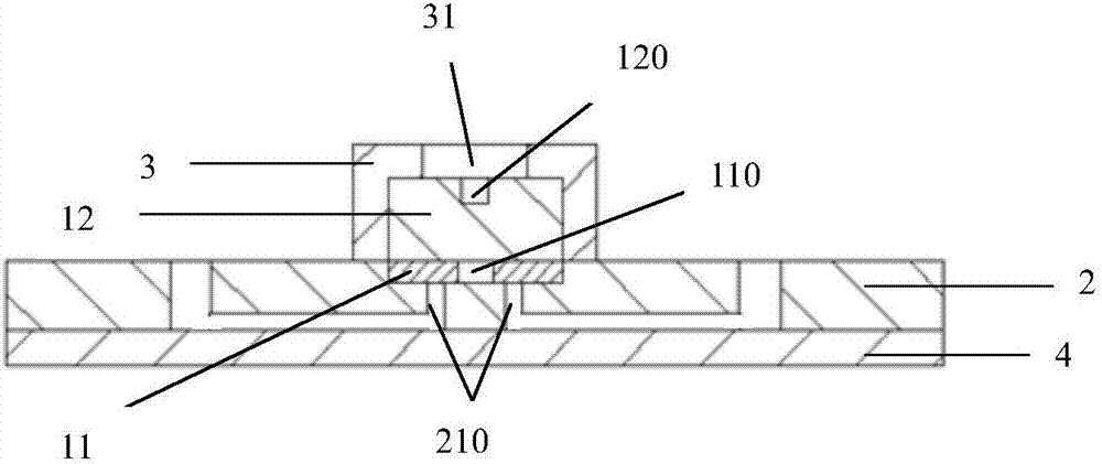
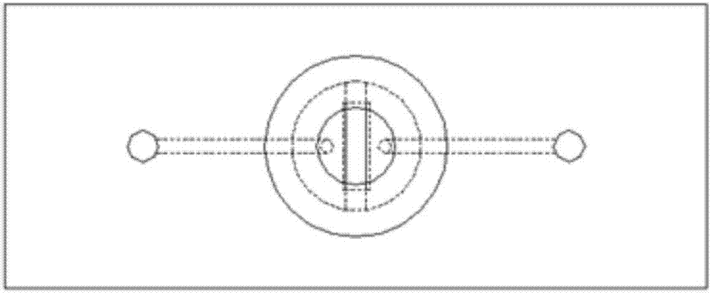
[0045] A microfluidic chip with a rotary valve structure, including a valve core, a substrate and a bottom sheet, one surface of the substrate is bonded to the bottom sheet, and the other surface of the substrate is provided with a valve chamber and a flow channel, The valve chamber is provided with at least two valve chamber through holes, and each of the valve chamber through holes is respectively connected to the flow channel, and the substrate is also provided with an inlet and an outlet respectively connected to the flow channel; the valve The core includes a sealing layer and a supporting layer, the sealing layer is arranged in the valve chamber, the supporting layer is arranged on the sealing layer, and the sealing layer is provided with a conversion channel; when the supporting layer rotates, it drives the The sealing layer is rotated so that the conversion channel communicates with at least two through holes of the valve chamber.

[0046] The above-mentioned valve cha...

Embodiment 2

[0053] On the basis of embodiment 1, the sealing layer is an elastic polymer material; the total height of the supporting layer and the sealing layer is greater than the depth of the valve core accommodation cavity. With this technical solution, the sealing layer is in a compressed state, which ensures that the reagent will not volatilize or leak when flowing through the conversion channel of the sealing layer.

[0054] Further, the elastic polymer material is one of thermoplastic elastomer or rubber. The use of thermoplastic elastomer or rubber firstly utilizes its advantages of corrosion resistance, high and low temperature resistance, wear resistance and low price, and secondly utilizes its advantages of being elastic and not easily deformed after compression.

[0055] Further, the support layer is one of polycarbonate, cycloolefin copolymer, thermoplastic elastomer, copper or stainless steel. The supporting layer and sealing layer may be of the same or different materials...

Embodiment 3

[0073] On the basis of embodiment 2, this embodiment combines Figure 1-Figure 5 The present invention will be described.

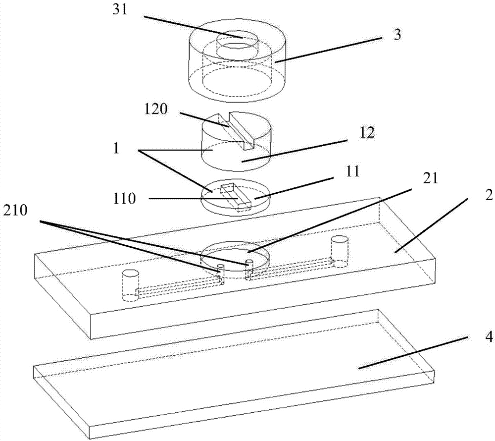
[0074] Such as Figure 1-Figure 3 A microfluidic chip with a rotary valve structure shown includes a valve core 1 , a substrate 2 , a gland 3 and a base 4 . The maximum thickness of the substrate 2 is 5mm, the thickness of the gland 3 is 2mm, and the thickness of the bottom sheet 4 is 1mm. The substrate 2, the gland 3 and the bottom sheet 4 are all made of polycarbonate material. The substrate 1 , the gland 3 and the bottom sheet 4 are formed by injection molding respectively.

[0075] The negative film and the base film are combined by chemical glue bonding. With this technical solution, the connection between the pressing cover and the substrate is firm.

[0076] The substrate 2 is provided with a valve chamber 21 and a flow channel, the valve chamber 21 is on the top of the substrate 2, the flow channel is at the bottom of the substrate 2, and the ...


PUM


Abstract

A microfluidic chip with a rotary valve structure includes a valve core, a substrate and a base plate, one surface of the substrate is attached to the base plate, the other surface of the substrate is provided with a valve chamber and a flow passage, the valve chamber is provided with at least two valve chamber through holes, each valve chamber through hole is respectively connected with the flow passage, the substrate is also provided with an inlet and an outlet respectively connected the flow passage, the valve core comprises a sealing layer and a support layer, the sealing layer is arranged in the valve chamber, the support layer is arranged on the sealing layer, the sealing layer is provided with a switching channel; and the support layer rotates to drive the rotation of the sealing layer for communication of the switching channel with the at least two valve chamber through holes. Free conversion and opening and closing of different flow paths can be realized only by use of one valve core, the control requirements of various flow paths can be met, production efficiency is improved; the control of the flow paths can be realized only by rotating of the valve core, and the control method is simple and efficient.

Description

technical field [0001] The invention relates to the technical field of nucleic acid amplification and detection, in particular to a microfluidic chip with a rotary valve structure. Background technique [0002] Microfluidic chip is based on micro-electromechanical processing technology, which forms a network on the chip by micro-pipelines, and runs through the entire system with controllable micro-fluidic channels to complete various biological and chemical processes. In the early stage of the development of microfluidic chip technology, chip capillary electrophoresis was the mainstream technology, and the chip used was simple in structure and single in function; Important biological and chemical processes such as reaction and cell lysis have become new hotspots. With the development of the industry, the technical application of microfluidic chips has entered the stage of clinical application, involving complex processes such as reagent mixing, reaction, and pretreatment. ...

Claims


Application Information

Patent Timeline
Patent Type & Authority Applications(China)
IPC IPC(8): B01L3/00
CPCB01L3/5027B01L2400/0644
Inventor 张国豪李永峰马涛
Owner BEIJING BAIKANGXIN BIOLOGICAL SCI & TECH
Why Eureka
Try Eureka