Power battery ultrasonic welding equipment

An ultrasonic welding and power battery technology, which is applied in welding equipment, non-electric welding equipment, metal processing equipment, etc., can solve the problems of low welding precision and good product rate, high production cost and failure rate, and low welding automation procedures, and achieve the goal of welding Improve efficiency and welding precision, high degree of automation, reduce production cost and failure rate

Active Publication Date: 2017-08-29
CONTEMPORARY AMPEREX TECH CO +1
View PDF9 Cites 24 Cited by
  • Summary
  • Abstract
  • Description
  • Claims
  • Application Information

AI Technical Summary

Problems solved by technology

[0003] In summary, the main purpose of the present invention is to solve the problem that the existing power battery welding automation program is not high, the production efficiency, welding accuracy and yield are low, the production cost and failure rate are high, and it cannot meet the needs of mass battery production. To solve the technical problem of demand, and provide a power battery ultrasonic welding equipment

Method used


Image

  • Power battery ultrasonic welding equipment
  • Power battery ultrasonic welding equipment
  • Power battery ultrasonic welding equipment

Examples


Embodiment Construction

[0041] The following examples are further explanations and supplements to the present invention, and will not constitute any limitation to the present invention.

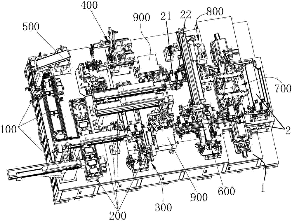
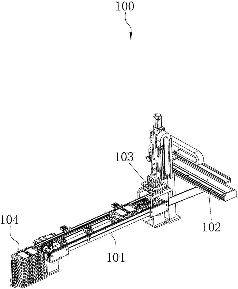
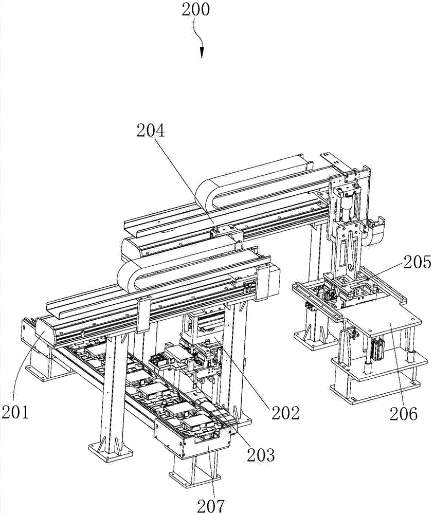
[0042] Such as Figure 1 to Figure 14 As shown, the power battery ultrasonic welding equipment of the present invention includes: a workbench 1, a feeding assembly line, a discharging assembly line, a tray feeding assembly 100, a cell feeding assembly 200, a connecting piece feeding assembly 300, a film assembly 400, an electrical Core blanking assembly 500 , reflow line body 2 , multiple clamps 21 , clamp positioning assembly 22 , protective sheet loading assembly 600 , ultrasonic welding assembly 700 , resistance welding assembly 800 and platen pick-and-place assembly 900 . Wherein, the feed line and the discharge line (not shown in the figure) are respectively set at the inlet and outlet of the workbench 1 (not shown in the figure), the tray loading assembly 100, the cell loading Component 200, connecting sheet ...


PUM


Abstract

The invention discloses power battery ultrasonic welding equipment. The power battery ultrasonic welding equipment comprises a working table, a tray feeding assembly, a cell feeding assembly, a connecting link feeding assembly, a film-pasting assembly, a cell discharging assembly, a protecting plate feeding assembly, an ultrasonic welding assembly, an electric resistance welding assembly and pressing plate pick-and-place assemblies, wherein the tray feeding assembly, the cell feeding assembly, the connecting link feeding assembly and the film-pasting assembly are arranged on the working table, the tray feeding assembly is used for feeding trays, and the cell feeding assembly is used for positioning cells; the connecting link feeding assembly is used for feeding copper and aluminum connecting links into fixtures, the film-pasting assembly is used for pasting blue glue on the welding area, and the cell discharging assembly is used for outputting the cells pasted with the film; and the protecting plate feeding assembly used for feeding protecting plates, the ultrasonic welding assembly used for compressing and welding positioned lugs, connecting links and protecting plates, the electric resistance welding assembly used for carrying out repair-welding on ultrasonically welded copper poles, and the pressing plate pick-and-place assemblies which are symmetrically arranged on the two sides of a return line body, and are used for transferring pressing plates into the fixtures or disassembling the pressing plates are arranged on the periphery of the return line body. According to the power battery ultrasonic welding equipment, the technical problems that the degree of welding automation of an existing power battery is not high, the manufacturing efficiency, the welding precision and the yield are low, and the manufacturing cost and the failure rate are high are solved; and the power battery ultrasonic welding equipment has the characteristics that the implementation is easy and the stability is high.

Description

【Technical field】 [0001] The invention relates to the technical field of ultrasonic welding, in particular to an ultrasonic welding device for power batteries. 【Background technique】 [0002] Lithium-ion power battery has become the green battery with the best comprehensive performance in the world because of its characteristics of high voltage, high capacity, low consumption, no memory effect, no pollution, small size, low internal resistance, low self-discharge, and many cycles. . It is widely used in many civil and military fields such as new energy vehicles, mobile phones, notebook computers, and tablet computers. Lithium-ion power batteries usually consist of three parts: battery cells, protection circuits and casings. The shell is divided into shell, cover plate, tab and copper / aluminum adapter piece. During the manufacturing process of the power battery, the positioned copper / aluminum adapters, tabs and gaskets need to be welded together on the battery cell. The...

Claims


Application Information

Patent Timeline
Patent Type & Authority Applications(China)
IPC IPC(8): B23K20/10B23K20/26
CPCB23K20/10B23K20/26
Inventor 杨华龙张小明闫战峰李毅牛增强韩金龙
Owner CONTEMPORARY AMPEREX TECH CO
Why Eureka
Try Eureka