
Special-purposed logic current type separation and link unipolar PWM method of AND-OR gate construction

A special logic and current-type technology, which is applied in the field of special logic-type current-type decoupled coupling unipolar PWM, can solve the problem that the single-phase high-frequency chain matrix rectifier cannot effectively solve the problem of safe commutation of the bidirectional switch tube, and avoid voltage overshoot , to achieve the effect of safe commutation

Inactive Publication Date: 2017-08-29
YANSHAN UNIV
View PDF2 Cites 2 Cited by
  • Summary
  • Abstract
  • Description
  • Claims
  • Application Information

AI Technical Summary

Problems solved by technology

[0005] The purpose of the present invention is to solve the problem that the modulation of the existing single-phase high-frequency chain matrix rectifier cannot effectively solve the problem of safe commutation of bidirectional switching tubes, etc., and propose a special logic for the "AND-OR" gate structure that can reliably realize the safe commutation of the single-phase high-frequency chain matrix rectifier Current mode decoupled unipolar PWM method

Method used


Image

  • Special-purposed logic current type separation and link unipolar PWM method of AND-OR gate construction
  • Special-purposed logic current type separation and link unipolar PWM method of AND-OR gate construction
  • Special-purposed logic current type separation and link unipolar PWM method of AND-OR gate construction

Examples


Embodiment Construction

[0031]The modulation method of the present invention will be further described below in conjunction with the accompanying drawings:

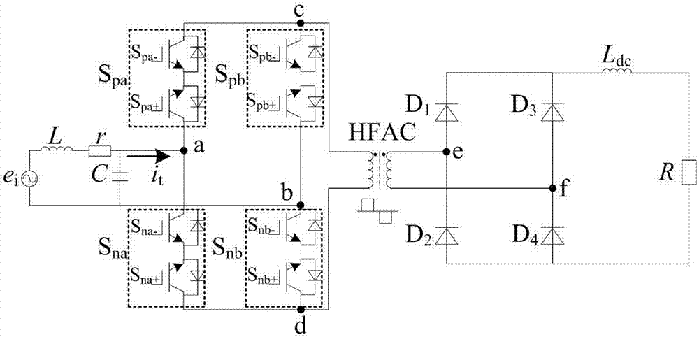
[0032] A kind of special-purpose logical type current-type dejunction coupling unipolar PWM method of "and-or" gate structure of the present invention, the single-phase high-frequency chain matrix rectifier circuit topological diagram that the present invention method adopts is as follows figure 1 As shown, it includes a pre-stage circuit, a high-frequency transformer HFAC and a post-stage circuit; the pre-stage circuit is composed of a voltage source e i , LC-type filter and single-phase matrix converter; the latter stage circuit is composed of uncontrolled rectification circuit, L-type filter L dc and the load R; the pre-stage circuit converts single-phase power-frequency AC into single-phase high-frequency AC, then couples and outputs it through the high-frequency transformer HFAC, and then outputs the pre-circuit through the uncontrolled rec...

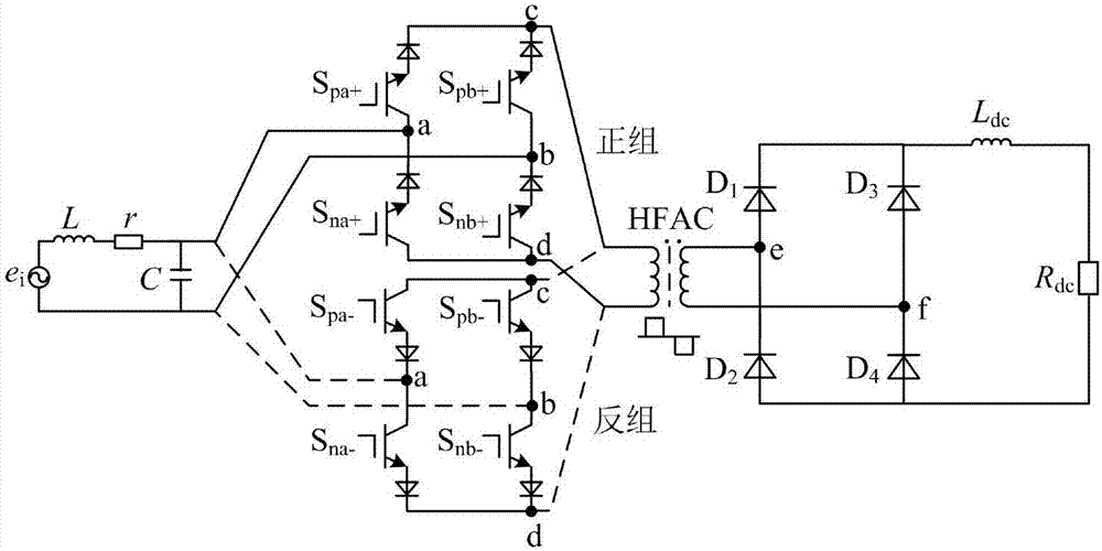

PUM


Abstract

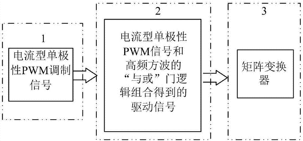
The invention relates to a special-purposed logic current type separation and link unipolar PWM method of an AND-OR gate construction. According to the method, a circuit topology of a single-phase high-frequency link matrix rectifier uses an LC type filter in the input side and an L type filter in the output side, so that the topology is a current type topology; modulation aimed at the single-phase high-frequency link matrix rectifier all uses current type modulation methods; and in a current type unipolar PWM signal generation link, two low-frequency driving signals and two high-frequency driving signals are generated, and four driving signals generated by current type PWM modulation and high-frequency square waves in 1 / 2 switching frequency are combined logically via special-purposed logic current type separation and link modulation of the AND-OR gate construction, and a driving signal for driving a pre-stage single-phase matrix converter of a high-frequency transformer of the single-phase high-frequency link matrix rectifier is obtained. Thus, a conversion problem of a bidirectional switch tube of the pre-stage matrix converter of the high-frequency transformer of the single-phase high-frequency link matrix rectifier is solved.

Description

technical field [0001] The invention relates to the field of modulation and control of electric power electronic power converters, in particular to a special logic-type current-mode decoupled coupling unipolar PWM method of an "AND-OR" gate structure of a single-phase high-frequency chain matrix rectifier. Background technique [0002] The rectifier is a topological device that converts AC power into DC power. The power frequency transformer used in the traditional rectifier system has problems such as large weight and volume, low efficiency, and high audio noise. Replacing the power frequency transformer with a high frequency transformer can not only Solve the above problems, and can realize the electrical isolation between the output and the input, output a wider range of voltage, improve the voltage transmission ratio and power density, reduce electromagnetic interference, improve the safety of electricity, etc., so that the power electronic converter system Performance h...

Claims


Application Information

Patent Timeline
Patent Type & Authority Applications(China)
IPC IPC(8): H02M7/219
CPCH02M7/219H02M1/0067
Inventor 王跃鹏郑倩男吴晓雨李春蕾梁晨阳
Owner YANSHAN UNIV
Learn More