
Coprime array adaptive wave beam shaping method based on covariance matrix virtual domain discrete reconstruction

A covariance matrix, adaptive beam technology, applied in the field of signal processing, can solve problems such as limited degrees of freedom

Active Publication Date: 2017-08-29
ZHEJIANG UNIV
View PDF3 Cites 9 Cited by
  • Summary
  • Abstract
  • Description
  • Claims
  • Application Information

AI Technical Summary

Problems solved by technology

[0006] The purpose of the present invention is to solve the problem of limited degrees of freedom existing in the existing adaptive beamforming method, and propose a coprime array adaptive beamforming method based on the discretization reconstruction of the virtual domain of the covariance matrix, and make full use of the characteristics of the coprime array Improve the degree of freedom performance of the adaptive beamformer, and design the weight vector of the beamformer based on the coprime array physical antenna elements, thereby effectively reducing the hardware and computational complexity of the overall system, and improving the degree of freedom and output performance of the beamforming method

Method used


Image

  • Coprime array adaptive wave beam shaping method based on covariance matrix virtual domain discrete reconstruction
  • Coprime array adaptive wave beam shaping method based on covariance matrix virtual domain discrete reconstruction
  • Coprime array adaptive wave beam shaping method based on covariance matrix virtual domain discrete reconstruction

Examples


example 1

[0087] Simulation example 1: The virtual domain spatial spectrum P of the coprime array proposed by the present invention v (θ) is compared with the Capon space spectrum using a uniform array such as Figure 4 As shown, the signal-to-noise ratio is 30dB, and the number of sampling snapshots is L=500. The vertical solid line in the figure represents the desired signal direction, and the vertical dotted line represents the interference direction. Since the number of incident signal sources is greater than the number of physical antenna elements, the degree of freedom performance of the uniform array method is limited by the number of physical antenna elements, and cannot effectively distinguish all incident signal sources at the same time; in contrast, mutual Mass Array Virtual Domain Spatial Spectrum P v (θ) enables efficient estimation of all signal sources. It can be seen that the use of coprime array virtual domain equivalent signals can increase the degree of freedom of ...

example 2

[0088] Simulation Example 2: The beam pattern of the method proposed by the present invention is compared with the uniform array ideal beam pattern and the coprime array ideal beam pattern as shown in Figure 5. The vertical solid line in the figure represents the desired signal direction, and the vertical dotted line represents the interference direction. The ideal beam pattern of a uniform array is shown in Figure 5(a). Due to the limited degree of freedom performance, the method using a uniform array can only form 9 nulls even in an ideal situation. In addition, because it cannot effectively distinguish all interference source, its main lobe is not precisely aligned with the desired signal direction; in contrast, the coprime array ideal beam pattern shown in Figure 5(b) can form nulls in all interference directions, and guarantee The signal direction forms the main lobe, which shows that the degree of freedom performance of the adaptive beamforming method using coprime arrays...

example 3

[0089] Simulation Example 3: Comparison of the output SINR performance between the proposed method of the present invention and the uniform array sparse reconstruction method Image 6 and Figure 7 shown. At the same time, the optimal value of the output SINR is also given in the figure as a reference. For each set of parameter values, the number of Monte Carlo experiments is 1000. Fig. 5 is the graph of the relationship between the output SINR and the input SNR, and the number of sampling snapshots is set to L=500; it can be seen that the trend and the optimum of the output SINR of the proposed method of the present invention The values ​​remain consistent and outperform uniform array sparse reconstruction methods. Image 6 is the relationship curve between the output SINR and the number of sampling snapshots, and the input SNR is set to 30dB; due to the limited performance of the degree of freedom, the output SINR of the uniform array sparse reconstruction method varies w...


PUM


Abstract

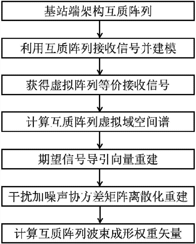
The invention discloses a coprime array adaptive wave beam shaping method based on covariance matrix virtual domain discrete reconstruction, wherein the method mainly settles problems of limited freedom performance and output performance reduction in prior art. The method comprises the following steps of (1), constructing a coprime array at a base station end; (2), receiving a signal by means of the coprime array and modeling; (3), obtaining a virtual array equivalent receiving signal; (4), calculating a coprime array virtual domain spatial spectrum; (5), reconstructing an anticipated signal guiding vector; (6), performing discrete reconstruction of an interference and noise covariance matrix; and (7), calculating a coprime array wave beam shaping weight vector. The coprime array adaptive wave beam shaping method sufficiently utilizes an advantage that the coprime array can improve freedom, and calculates the virtual domain spatial spectrum through an equivalent virtual signal statistics amount, thereby realizing parameter estimation. Furthermore a reconstruction concept is utilized for realizing designing of a coprime array physical antenna array weight vector, thereby effectively improving freedom and output performance of an adaptive wave beam shaper. Furthermore the coprime array adaptive wave beam shaping method can be used for directional transmission and receiving of signals.

Description

technical field [0001] The invention belongs to the technical field of signal processing, and in particular relates to beamforming for radar signals, acoustic signals and electromagnetic signals, specifically a coprime array adaptive beamforming method based on covariance matrix virtual domain discretization reconstruction, which can be used for directional transmission of signals and receive. Background technique [0002] Beamforming is an important branch in the field of array signal processing. Taking the receiving end as an example, beamforming uses the combination of antenna technology and various digital signal processing technologies to accumulate the weights of the signals received by multiple antenna elements to enhance the array gain of the desired signal and suppress interference and noise. Adaptive beamforming can adjust the beamforming weight vector according to the external environment to ensure the stability and robustness of the system. It has important appl...

Claims


Application Information

Patent Timeline
Patent Type & Authority Applications(China)
IPC IPC(8): H04B7/06H01Q21/08H01Q21/00
CPCH01Q21/00H01Q21/08H04B7/0617
Inventor 史治国周成伟陈积明
Owner ZHEJIANG UNIV
Learn More