A joint monitoring method based on lidar and video
A lidar and video technology, used in location-based services, closed-circuit television systems, and re-radiation of electromagnetic waves, which can solve the problems of inaccurate intrusion detection and high maintenance costs for radar and video surveillance systems
- Summary
- Abstract
- Description
- Claims
- Application Information
AI Technical Summary
Problems solved by technology
Method used
Image
Examples
specific Embodiment approach 1
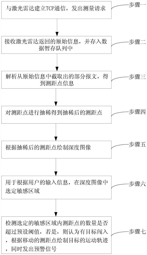
[0035] Specific implementation mode one: the joint monitoring method based on lidar and video in this implementation mode, such as figure 1 shown, including:
[0036] Step 1. Establish TCP communication with the lidar and send a measurement request;
[0037] Step 2, receiving the original information returned by the laser radar, and storing the original information in the data temporary storage queue;
[0038] Step 3, analyzing the partial message intercepted from the original information to obtain the distance measuring point information;
[0039] Step 4, performing thinning processing on the ranging points to obtain the thinned ranging points;
[0040] Step 5. Draw a depth image according to the thinned distance measurement points; the depth image has a selected monitoring area.
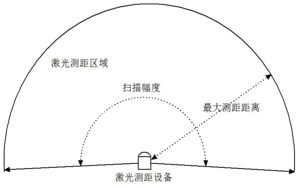
[0041] In this embodiment, firstly according to figure 2 The scanning principle of the laser radar can realize the monitoring function. This part includes three threads: data acquisition thre...
specific Embodiment approach 2
[0048] Specific implementation mode two: the difference between this implementation mode and specific implementation mode one is:
[0049] The thinning algorithm is the Douglas Peuker algorithm.
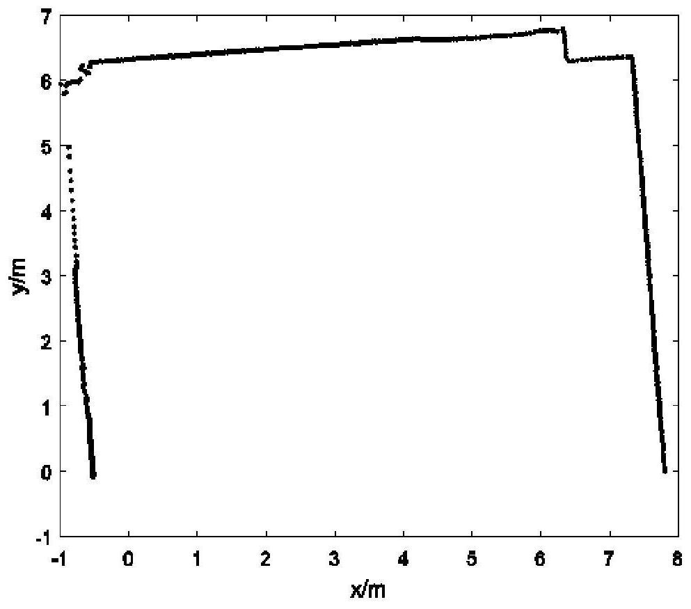
[0050]Since the lidar collects a large number of ranging points in the indoor environment, for example, when the angular resolution is 0.5° and the scanning range is 190°, the number of sampling points has reached 381. Compared with the typical geometric structure of the indoor environment, such as the wall It is too complicated for the straight line and even the curve of the body, which is not conducive to the real-time processing of data, and it is also inconvenient to observe. In fact, when processing vectorized data, there are often a lot of repeated data in the records, which brings a lot of inconvenience to further data processing. On the one hand, redundant data wastes more storage space, and on the other hand, the graph to be expressed is not smooth or does not meet the stan...
specific Embodiment approach 3
[0056] Specific implementation mode three: the difference between this implementation mode and specific implementation mode one or two is: after step six, it also includes:
[0057] Step 7: Obtain the video signal of the camera, and display the video signal, the depth image and the target's motion track in the same interface
[0058] The advantage of this setting is that the monitoring personnel can obtain two kinds of monitoring information at the same time, which increases the convenience and the monitoring effect is more intuitive. Video surveillance can use industrial cameras to collect video, use x264 compression coding for video coding, and use error-free control UDP for video packet transmission in the LAN. The flow chart of the video surveillance process is as follows: Figure 4 shown.
[0059] Other steps and parameters are the same as those in Embodiment 1 or Embodiment 2.
PUM
 Abstract
Description
Claims
Application Information
 - R&D
- Intellectual Property
- Life Sciences
- Materials
- Tech Scout
- Unparalleled Data Quality
- Higher Quality Content
- 60% Fewer Hallucinations
Browse by: Latest US Patents, China's latest patents, Technical Efficacy Thesaurus, Application Domain, Technology Topic, Popular Technical Reports.
© 2025 PatSnap. All rights reserved.Legal|Privacy policy|Modern Slavery Act Transparency Statement|Sitemap|About US| Contact US: help@patsnap.com


