
Self-propelled leaf vegetable harvester

A self-propelled, harvester technology, applied in the field of harvesters, can solve the problems of large machine body, poor cutting adaptability, uneven cutting, etc., and achieve the effect of ensuring harvest quality, avoiding cutting loss, and avoiding damage and damage.

Inactive Publication Date: 2017-09-01
NANJING AGRI MECHANIZATION INST MIN OF AGRI
View PDF14 Cites 9 Cited by
  • Summary
  • Abstract
  • Description
  • Claims
  • Application Information

AI Technical Summary

Problems solved by technology

[0002] According to the applicant's understanding, the typical structure of the existing leaf vegetable harvester such as cabbage is disclosed in the Chinese patent application document with the application number CN201220165512. Vegetables are damaged, and need to be fed in rows, the requirements for the row spacing of planted vegetables are relatively high, and the adaptability is not strong
[0003] In addition, the existing leaf vegetable harvester lacks the header cutting profiling system, which not only causes cutting waste and uneven cutting, but also has poor adaptability to uneven ground
For example, the technical scheme of the Chinese patent application with the application number CN201320278063.4 adopts the positioning distance between the cutting knife and the bottom end of the conveyor belt to realize cutting of the roots of cabbage vegetables. The distance between the knife and the conveyor belt is fixed, so the cutting height Unable to adjust, poor cutting adaptability
[0004] Moreover, the existing leaf vegetable harvester adopts the method of hanging headers on the side of the tractor and harvesting in a single row. The harvesting efficiency is low and does not conform to the planting agronomy of leaf vegetables in one ridge and two rows in my country. The machine body is large in size and is not suitable for scattered land in my country. , The status quo of small field area

Method used


Image

  • Self-propelled leaf vegetable harvester
  • Self-propelled leaf vegetable harvester
  • Self-propelled leaf vegetable harvester

Examples


Embodiment 1

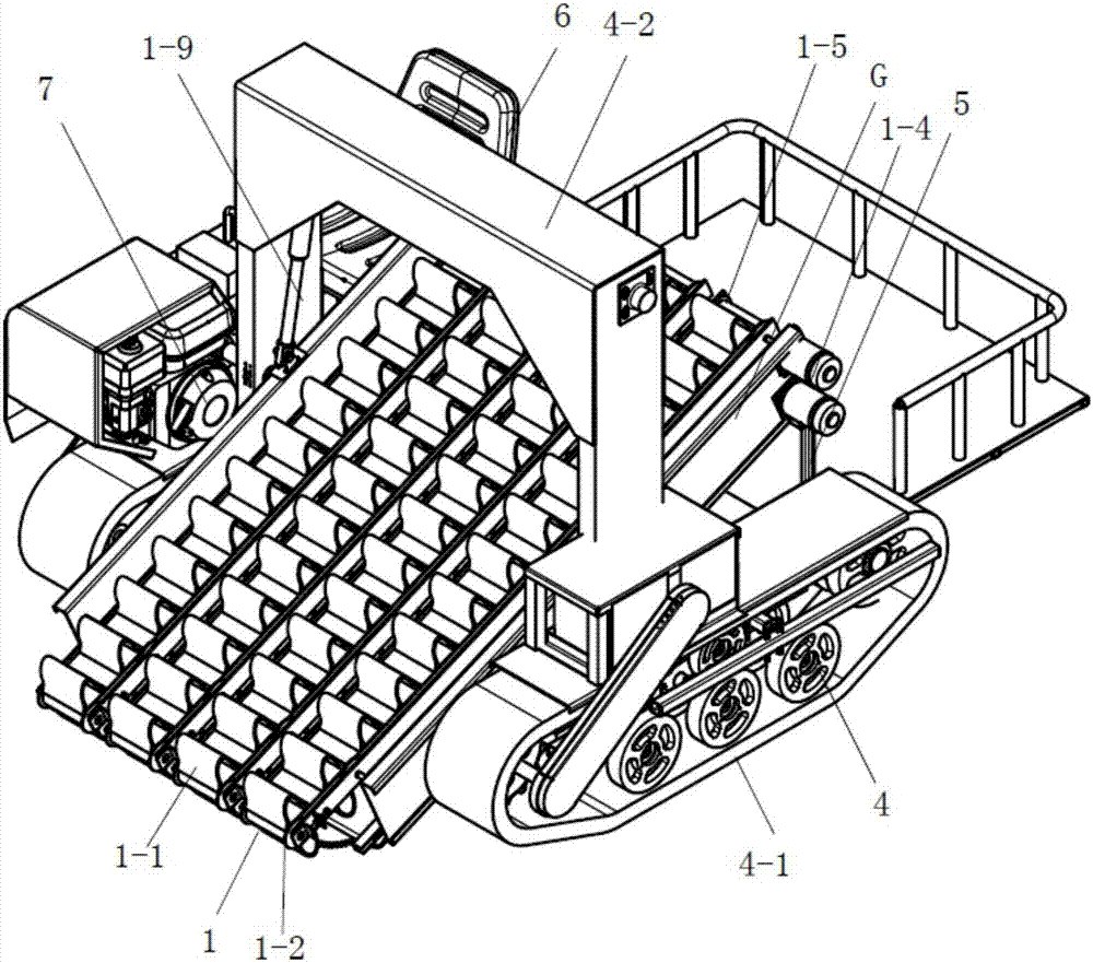
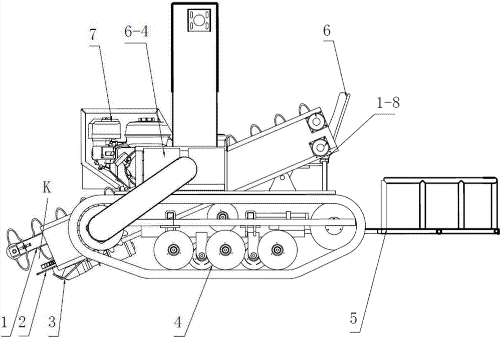
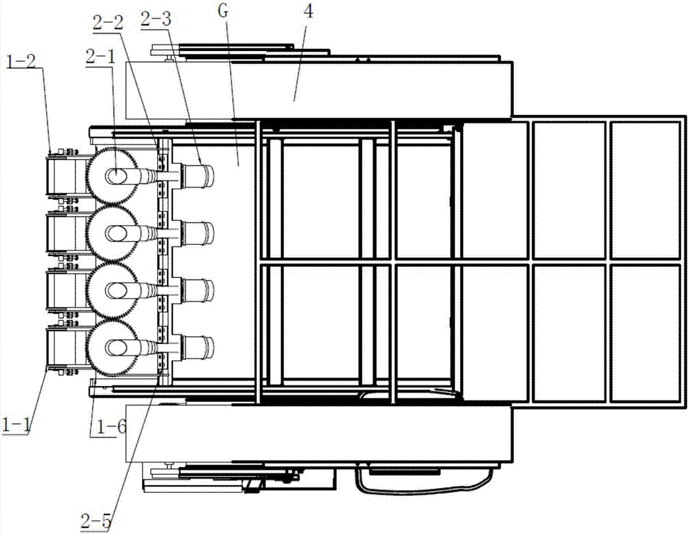
[0018] The basic structure of the self-propelled leaf vegetable harvester of the present embodiment is as follows: figure 1 and figure 2 As shown, it includes a gantry 4-2 straddling the crawler chassis 4 (for the specific structure of the gantry 4-2, please refer to the Chinese patent document with application number 200910026164.0) and a driving system 6 located on one side of the crawler chassis. The profiling conveying device 1 positioned on the header frame G is mounted on the crawler chassis 4 .

[0019] The front end of the profiling conveying device 1 is positioned at the front and bottom of the crawler chassis 4 , and the rear end extends through the gantry 4 - 2 and is positioned at the rear top of the crawler chassis 4 . The profiling conveying device 1 is made up of four pairs of vertically encircling lower lifting conveyer belts 1-6 and vertically encircling upper corrugated conveyer belts 1-1 which are paired to form a spaced profiling space K. The entry end o...


PUM


Abstract

The invention relates to a self-propelled leaf vegetable harvester, and belongs to the technical field of agricultural harvesters. The harvester comprises a door-shaped frame crossing a caterpillar base plate and a driving system located at one side of the caterpillar base plate, a copying conveying device located on a header frame is installed on the caterpillar base plate, the front end of the copying conveying device is located on the lower portion of the caterpillar base plate, and the rear end of the copying conveying device extends to penetrate through the door-shaped frame to be located above the back of the caterpillar base plate; the copying conveying device is composed of a vertically surrounded lower lifting conveying belt and an upper waveform conveying belt matched with the lower lifting conveying belt to form a spaced copying space, the entering end of the lifting conveying belt lags behind the input end of the waveform conveying belt, and a disc cutting device is installed below the portion between the input end of the waveform conveying belt and the entering end of the lifting conveying belt. Accordingly, leaf vegetables can be protected through the copying space of the waveform conveying belt, leaf vegetable breakage and cutting loss are effectively avoided, feeding in a line alignment mode is not needed, and the harvesting quality is guaranteed while efficient harvesting is conducted.

Description

technical field [0001] The invention relates to a harvester, in particular to a self-propelled leaf vegetable harvester, which belongs to the technical field of agricultural harvesting machinery. Background technique [0002] According to the applicant's understanding, the typical structure of the existing leaf vegetable harvester such as cabbage is disclosed in the Chinese patent application document with the application number CN201220165512. Vegetables are damaged and need to be fed in rows. The requirements for the row spacing of the grown vegetables are relatively high, and the adaptability is not strong. [0003] In addition, the existing leafy vegetable harvester lacks the header cutting profiling system, which not only causes cutting waste and uneven cutting, but also has poor adaptability to uneven ground. For example, the technical scheme of the Chinese patent application with the application number CN201320278063.4 adopts the positioning distance between the cutt...

Claims


Application Information

Patent Timeline
IPC IPC(8): A01D45/00A01D57/20
CPCA01D45/00A01D57/20
Inventor 肖宏儒金月许萌宋志禹梅松杨光赵映
Owner NANJING AGRI MECHANIZATION INST MIN OF AGRI
Learn More