
A self-deflecting mixer

A mixer and deflection technology, which is applied to mixers with rotating stirring devices, mixers, dissolving, etc., can solve the problems of affecting stirring efficiency, safety accidents, and large resistance of stirring paddles, so as to speed up the feedback speed and reduce the contact time , Easy mixing effect

Active Publication Date: 2019-06-04
JINHUA GAOJIU ELECTRIC EQUIP CO LTD
View PDF8 Cites 0 Cited by
  • Summary
  • Abstract
  • Description
  • Claims
  • Application Information

AI Technical Summary

Problems solved by technology

[0003] The existing stirring drilling tool is composed of an integrated fuselage, a stirring rod, and an operating handle. The fuselage is used to provide power. When putting the mixer drill into the container, in order to ensure that the material is evenly stirred, the operator needs to continuously move the stirring paddle to different positions in the mixing container through the yaw operation handle for stirring. When stirring relatively viscous materials, the resistance of the paddle Large, the reaction force of the material to the stirring paddle is transmitted to the operating handle through the stirring paddle, stirring rod, and the fuselage. The huge reaction force makes the operating handle vibrate seriously, making it difficult for the operator to grasp, making it difficult to move the mixing drill, and may even cause safety hazards. Accidents, seriously affecting the mixing efficiency

Method used


Image

  • A self-deflecting mixer
  • A self-deflecting mixer
  • A self-deflecting mixer

Examples


Embodiment 1

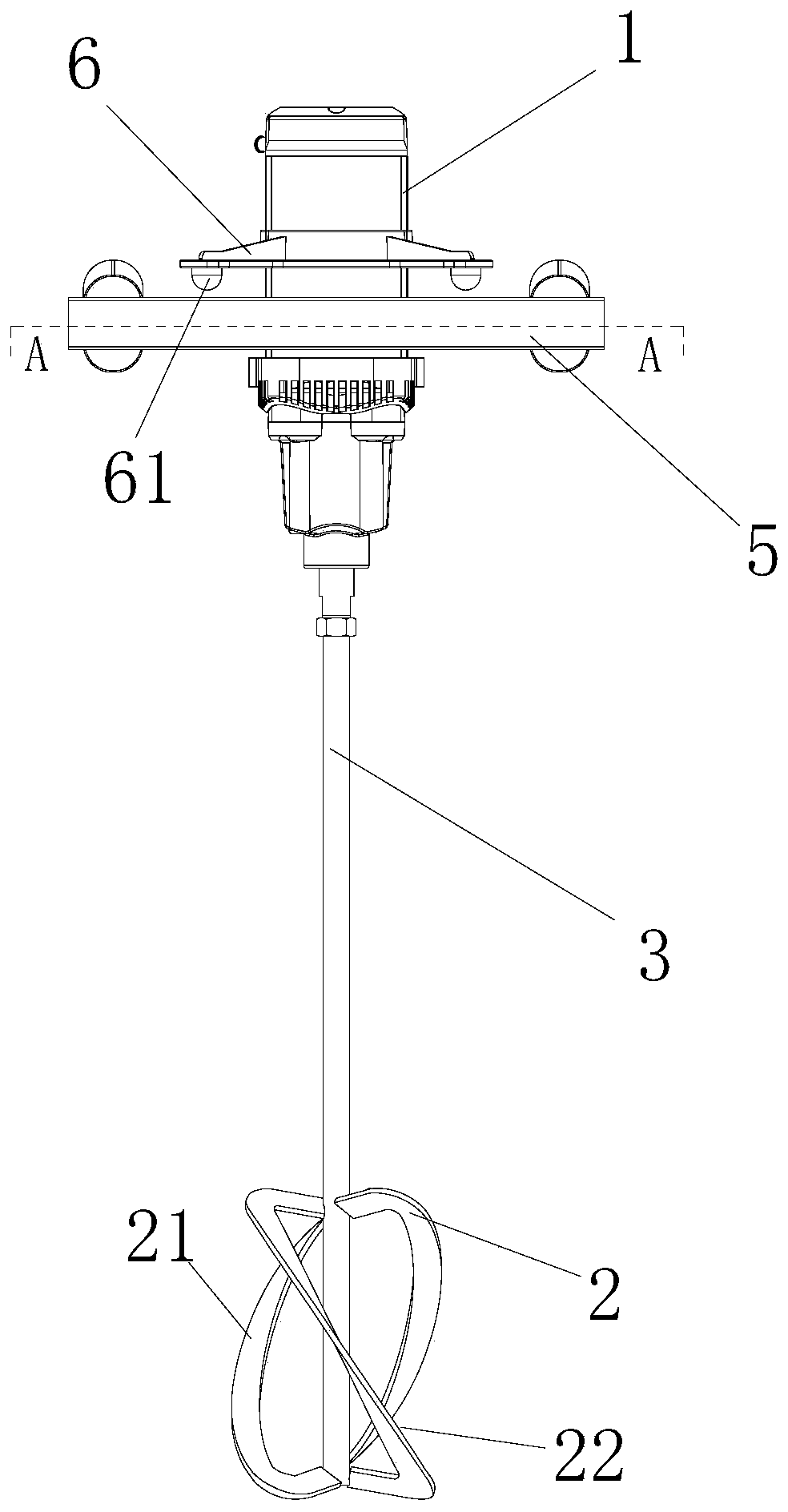
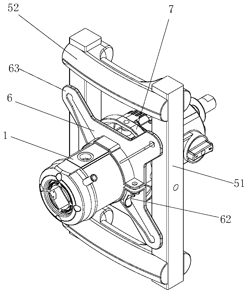
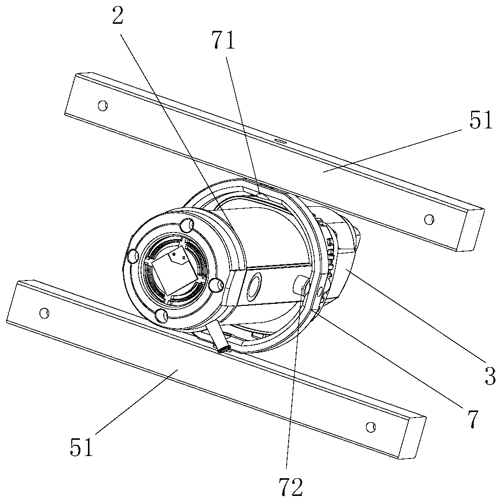
[0025] Example 1 as Figure 1 to Figure 6 As shown, the self-deflecting mixer of this embodiment includes: an operating handle 5, a stirring rod 3, and a body 1; the bottom end of the body 1 is connected to the stirring rod 3 for providing rotational power to the stirring rod 3, The bottom end of the asymmetrical paddle 2 is connected, and the paddle 2 includes two C-shaped paddles 21 and one S-shaped paddle 22, and the two ends of the C-shaped paddle 21 are fixedly connected with the stirring rod 3, and the S-shaped paddle The two ends of 22 are fixedly connected with the stirring rod 3, and the weight difference on both sides of the stirring rod 3 makes the center of gravity of the stirring paddle 2 not coincide with the axis of the stirring rod 3, so as to ensure that the stirring rod 3 is tilted when it is stationary.

[0026] The operating handle 5 is a frame-type operating handle composed of two horizontal braces 51 and two vertical braces 52. The fuselage 1 passes throu...

Embodiment 2

[0030] On the basis of embodiment 1, the difference between this embodiment and embodiment 1 is that, as Figure 8 As shown, a limit spring 65 (replacing the hemispherical contact portion 61 in Embodiment 1) is vertically provided on the lower end surface of each limit claw 63, and the bottom end of the limit spring 65 is connected with the upper end of the frame-type operating handle cross brace 51. The end faces are fixedly connected, when the fuselage 1 drives the limit clamp 6 to deflect, as Figure 9 As shown, the limit spring 65 on one side of the fuselage is compressed to produce elastic deformation, and the limit spring 65 on the other side is stretched to produce elastic deformation. Finally, the fuselage 1 deflects in the opposite direction under the action of the limit springs 65 on both sides of the fuselage 1 , thereby changing the deflection direction of the fuselage 1 .


PUM


Abstract

The invention relates to a self-deviating mixer, which includes a fuselage, a stirring rod, and an operating handle; The symmetrical sides of the outer wall of the swing ring are pivotally connected to the operating handle so that the swing ring can swing in the operating handle; the symmetrical sides of the fuselage and the inner wall of the swing ring are pivotally connected so that the body can swing The swing ring swings inside, and the setting of the swing ring can make the reaction force of the material on the stirring rod be transmitted to the swing ring, which can be absorbed by the swing ring, so as to reduce the vibration of the operating handle and make it easy for the operator to operate; the bottom of the stirring rod The stirring paddle is arranged at the end, and the stirring paddle is an asymmetrical stirring paddle, so that when the stirring rod hangs down naturally in the deflection ring, there is an angle between the axial direction of the stirring rod and the direction of gravity, so that when the stirring rod is stationary Tilt setting, when the body drives the stirring rod to rotate, the stirring rod rotates around the center of the yaw ring while rotating on its own.

Description

technical field [0001] The invention relates to the technical field of mixers, in particular to a self-deflecting mixer. Background technique [0002] Stirring is a common method to make materials mix evenly. It is mainly aimed at fluids. According to the phase, it is divided into gas, liquid, semi-solid and granular solid stirring. It is widely used in various industries, such as food processing industry, construction industry, chemical industry, etc. Industry; especially in the construction of building decoration projects, when gypsum and putty powder are used, water or adhesive glue should be added to stir them into a paste; diatom mud, etc. also need to be stirred before use. Due to the structure of their own products, construction mixers cannot be used. For stirring, use a small stirring drill for stirring. [0003] The existing stirring drilling tool is composed of an integrated fuselage, a stirring rod, and an operating handle. The fuselage is used to provide power. ...

Claims


Application Information

Patent Timeline
Patent Type & Authority Patents(China)
IPC IPC(8): B01F7/14B01F27/75
CPCB01F27/112B01F27/191B01F27/75
Inventor 孙宇航
Owner JINHUA GAOJIU ELECTRIC EQUIP CO LTD
Learn More