Grain drying machine

A technology for grain dryers and dryers, applied in grain drying, dryers, drying solid materials, etc., can solve the problems of insufficient drying space, high energy consumption of equipment, and increased costs, so as to prolong the heating time and meet the drying requirements. Requirements, the effect of ensuring cleanliness

Inactive Publication Date: 2017-09-01
HEFEI HUIZHI NEW MACHINERY TECH CO LTD
View PDF8 Cites 6 Cited by
  • Summary
  • Abstract
  • Description
  • Claims
  • Application Information

AI Technical Summary

Problems solved by technology

[0003] Natural drying is easy to be restricted by the influence of weather and space. In the main grain producing areas, due to the large output and insufficient drying space, the grain purchased by the grain depot often exceeds the safe water. This is the main factor leading to grain mildew, especially in grain. The purchase period is catching up with continuous cloudy days, and this is even more so. In addition, even if the moisture content of the grain does not exceed the safe moisture level when it is put into storage, due to the natural tide, the grain liquid needs to be dried regularly to ensure that the grain does not go moldy
[0004] However, most of the existing dryers are large and super-large, and are fixedly installed in the grain processing plant. The equipment has high energy consumption, low automation level, and large investment. Farmers must transport the grain to the grain processing plant to dry the grain. Dry, not only troublesome, but also increase the cost

Method used


Image

  • Grain drying machine

Examples


Embodiment Construction

[0021] Below in conjunction with specific embodiment, further illustrate the present invention. These examples are only for illustrating the present invention and are not intended to limit the scope of the present invention. In the description of the present invention, it should be noted that, unless otherwise clearly specified and limited, the terms "equipped with" and "connected" should be understood in a broad sense, for example, it can be a fixed connection or a detachable connection, or Integral connection; it can be mechanical connection or electrical connection; it can be direct connection or indirect connection through an intermediary, and it can be the internal communication of two components. Those of ordinary skill in the art can understand the specific meanings of the above terms in the present invention in specific situations.

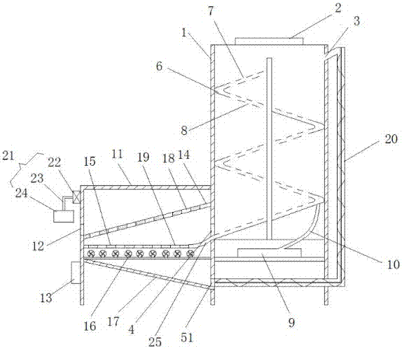
[0022] combined with figure 1 , to achieve the above object, the present invention is achieved through the following technical solution...


PUM


Abstract

The invention discloses a grain drying machine. The grain drying machine comprises a drying machine body, a first feeding inlet, a second feeding inlet, a first discharging outlet, a second discharging outlet and a third discharging outlet. The drying machine body has a hollow cavity, and a screw propulsion plate is arranged at the center of the inside of the drying machine body. A hollow chamber is formed in the screw propulsion plate. First exhaust outlets and second exhaust outlets are formed in the upper surface and the lower surface of the screw propulsion plate separately. A hot-air blower is arranged at the bottom of the drying machine body and further communicates with the screw propulsion plate through a hot-air pipeline. An analysis room is arranged at the left side of the drying machine body. The analysis room comprises an L-shaped support, a second discharging outlet and a PLC. A first tilted baffle, a material receiving plate, air blowers and a second tilted baffle are sequentially arranged inside the L-shaped support from top to bottom. The air blowers and the hot-air blower are electrically connected to the PLC. The grain drying machine has the advantages of being small in size, low in weight, convenient to transport, capable of achieving grain circulation drying, uniform in heating, high in drying efficiency and free of pollution.

Description

technical field [0001] The invention relates to the technical field of agricultural food preservation and processing, in particular to a grain dryer. Background technique [0002] Grain is a living organism, and moisture is the condition for its survival. Excessive moisture will induce the growth of insects and microorganisms, and easily cause heat generation, fermentation, deterioration and germination rate of food. Taking grain as an example, the moisture content of grain is 25%-30% when it is harvested, and it needs to be reduced to a safe moisture content of 10%-15% as soon as possible during storage. The grain in my country is harvested 1-3 times a year and needs to be stored for several years. At present, the control of grain moisture mainly includes natural drying and drying by grain dryers. [0003] Natural drying is easy to be restricted by the influence of weather and space. In the main grain producing areas, due to the large output and insufficient drying space, ...

Claims


Application Information

Patent Timeline
Patent Type & Authority Applications(China)
IPC IPC(8): F26B17/12F26B21/00F26B25/00F26B21/12
CPCF26B17/12F26B21/004F26B21/12F26B25/002F26B25/005F26B2200/06
Inventor 解正来
Owner HEFEI HUIZHI NEW MACHINERY TECH CO LTD
Why Eureka
Try Eureka