Marker positioning method and system of calibration plate image

A positioning method and positioning system technology, applied in the field of marker positioning, can solve the problems of weak robustness, low algorithm efficiency, long running time, etc., and achieve the effect of improving positioning efficiency, reducing debugging difficulty, and ensuring positioning accuracy.

Inactive Publication Date: 2017-09-01
SHENZHEN HUAHAN WEIYE TECH
View PDF2 Cites 15 Cited by
  • Summary
  • Abstract
  • Description
  • Claims
  • Application Information

AI Technical Summary

Problems solved by technology

[0004] At present, most of the existing landmark positioning algorithms perform sub-pixel edge extraction or contour extraction on the original image of the calibration plate, and perform ellipse fitting to extract the image coordinates of the center of the circle. Although the coordinates of the center of the circle can be accurately extracted, there are still the following deficiencies : To operate on the original image of the calibration board image, the algorithm efficiency is low and the running time is long when targeting the high-resolution calibration board image; when performing sub-pixel edge or contour extraction, there are many parameter settings, and the calibration needs to be repeatedly adjusted. For Debuggers have high professional knowledge requirements; high image quality requirements for calibration board images are very sensitive to noise and light effects, and the robustness is not strong

Method used


Image

  • Marker positioning method and system of calibration plate image
  • Marker positioning method and system of calibration plate image
  • Marker positioning method and system of calibration plate image

Examples


Embodiment Construction

[0048] The present invention will be further described in detail below through specific embodiments in conjunction with the accompanying drawings.

[0049] Definitions of terms used in the present invention:

[0050] An image pyramid is a structure for explaining images at multiple resolutions. An image pyramid is a collection of progressively lower resolution images arranged in a pyramid shape. The bottom image of the pyramid is a high-resolution representation, while the top is a low-resolution representation.

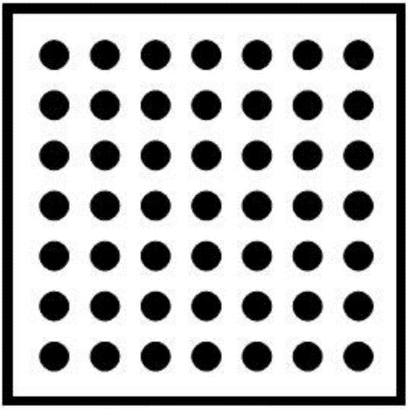
[0051] Region of interest (ROI, region of interest), in machine vision, image processing, outlines the area that needs processing from the processed image with the mode such as box, circle, ellipse, irregular polygon, adopts rectangular square in the present embodiment frame.

[0052] The present invention calculates the resolution size of the calibration board image (target image) to determine the required number of image pyramid layers; performs down-sampling of...


PUM


Abstract

The present invention discloses a marker positioning method and system of a calibration plate image. The method includes the following steps that: image pyramid layering is performed on the calibration plate image; binarization is performed from a topmost layer of image, a calibration plate area and a marker contour are searched in the binary image, if no calibration plate areas and marker contours are found out, the calibration plate area and the marker contour are further searched in a next layer of image until search is performed in the last layer or the calibration plate area and the marker contour are found out; and the bounding rectangle of the marker contour in the calibration plate area is calculated in the pyramid image of the searched calibration plate area, the bounding rectangle is mapped into the calibration plate image, so that a region of interest containing a marker is obtained, and the center coordinates of the marker are calculated. Therefore, contour search is performed from the top-layer low-resolution image, so that the calibration plate area and the marker contour can be found out, and the region of interest containing the marker can be positioned quickly and accurately, and positioning efficiency is improved.

Description

technical field [0001] The invention relates to the technical field of machine vision, in particular to a method and a system for locating markers on a calibration plate image. Background technique [0002] In the era of Industry 4.0, precision measurement and detection based on machine vision is a very important research field, whether it is in traditional manufacturing, 3C electronics industry or aerospace field, it has very broad application prospects. Camera calibration is the basis for machine vision to obtain precise measurement data. Camera calibration is the process of solving the internal and external parameters of the camera through the correspondence between the world coordinate system and the image coordinate system. The accuracy of the actual measurement data depends on the internal parameters of the camera. The accuracy of parameters and external parameters, then in the final analysis, a set of accurate correspondence between the world coordinate system and the...

Claims


Application Information

Patent Timeline
Patent Type & Authority Applications(China)
IPC IPC(8): G06T7/80G06T7/136G06T7/66
CPCG06T7/80G06T7/136G06T7/66G06T2207/20016
Inventor 黄涛
Owner SHENZHEN HUAHAN WEIYE TECH
Why Eureka
Try Eureka