Optical injection-based CV-QKD system and sending end, receiving end and CV-QKD method
A technology of optical injection and sending end, which is applied in the field of quantum communication, can solve problems such as complex technical solutions, and achieve the effect of improving the coding rate, reducing additional noise, and simple solutions
- Summary
- Abstract
- Description
- Claims
- Application Information
AI Technical Summary
Problems solved by technology
Method used
Image
Examples
Embodiment 1
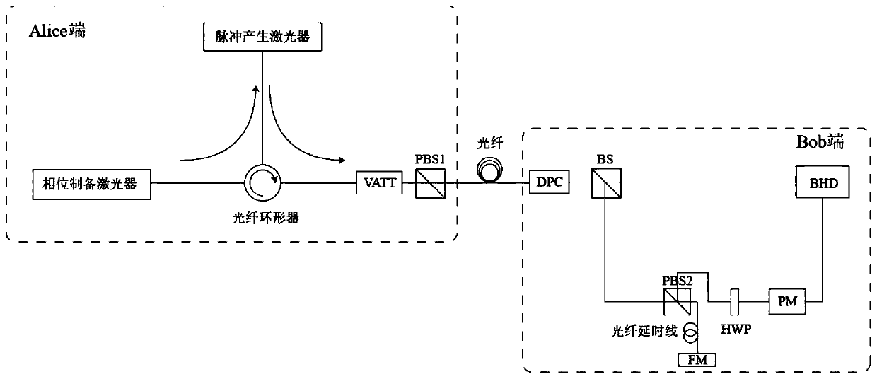
[0099] see figure 2 , the CV-QKD system of this embodiment includes a sending end (Alice end) and a receiving end (Bob end), and a phase modulation light source is provided in the sending end, and the phase modulation light source includes:
[0100] Phase preparation lasers for generating long pulses with phase difference information;
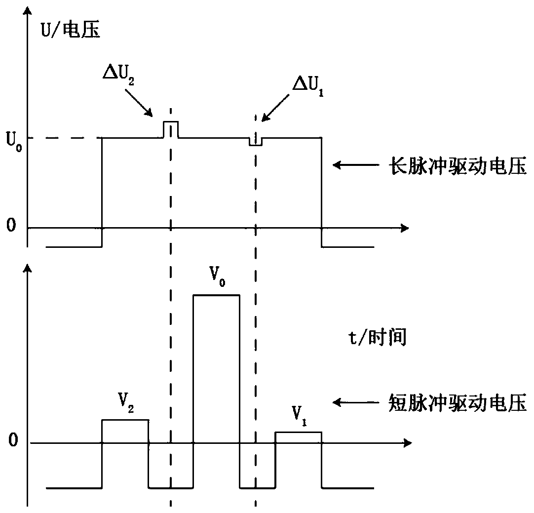
[0101] A pulse generating laser is used for receiving and being excited by the long pulse to generate a plurality of short pulses with corresponding phase differences, and at least one of the short pulses is used as a signal pulse.
[0102] A fiber optic circulator is used between the phase preparation laser and the pulse generation laser to control the direction of the optical signal.
[0103] The output end of the phase modulation light source is provided with a variable optical attenuator and a polarization beam splitter in turn, wherein one path of the horizontally polarized light in the polarization beam splitter is used as the output of...
Embodiment 2
[0127] see Figure 6 , in Embodiment 1, the amplitude modulation of the signal pulse is accomplished by adjusting the driving voltage of the pulse-generating laser. However, in this embodiment, the amplitude modulation is accomplished jointly by an external variable optical attenuator (VATT) and an amplitude modulator (AM).
[0128] At this time, the three pulse driving voltages in the pulse generating laser are all V0, and the driving voltages are no longer modulated. The subsequently generated pulses are modulated by VATT to greatly attenuate the intensity of the signal pulses (here, the definitions of signal pulses and local oscillator pulses are the same as those in Embodiment 1). The pulses then enter the AM, which Gaussian modulates the amplitude of the signal pulses according to the value of the corresponding random number pair.
[0129] The rest of the steps in this embodiment are the same as those in Embodiment 1, so they will not be described in detail.
Embodiment 3
[0131] On the basis of generating three short pulses at a time in this embodiment 1 and 2, it can be further extended to make one long pulse generate more short pulses, and the position of pulses in a pulse group in terms of timing is: weak, strong, weak.... Strength ("weak" means signal pulse, "strong" means local oscillator pulse), see Figure 7 . At this time, the phases of the signal pulses in the pulse group are modulated by the optical injection technique (same as that in Embodiment 1). The amplitude modulation can be performed by modulating the driving voltage of the pulse-generating laser in implementation 1, or by externally connecting VATT and AM in embodiment 2.
[0132] The remaining steps of this embodiment are the same as those of Embodiments 1 and 2, and will not be described in detail.
PUM
 Abstract
Description
Claims
Application Information
 - R&D
- Intellectual Property
- Life Sciences
- Materials
- Tech Scout
- Unparalleled Data Quality
- Higher Quality Content
- 60% Fewer Hallucinations
Browse by: Latest US Patents, China's latest patents, Technical Efficacy Thesaurus, Application Domain, Technology Topic, Popular Technical Reports.
© 2025 PatSnap. All rights reserved.Legal|Privacy policy|Modern Slavery Act Transparency Statement|Sitemap|About US| Contact US: help@patsnap.com


