Chamfering machining equipment and chamfering machining method for curved surfaces of orifices of oil holes of connecting rods

A technology of processing equipment and processing methods, applied in metal processing equipment, milling machine equipment, details of milling machine equipment, etc., can solve the problems of difficult to meet the use requirements of connecting rods, complicated processing equipment, low processing efficiency, etc., and achieve chamfering consistency. And the effect of surface roughness improvement, large feed rate and efficiency improvement

Pending Publication Date: 2017-09-05
四川普什宁江机床有限公司
View PDF5 Cites 3 Cited by
  • Summary
  • Abstract
  • Description
  • Claims
  • Application Information

AI Technical Summary

Problems solved by technology

[0005] In order to overcome the defects and deficiencies in the above-mentioned prior art, the present invention provides a kind of equipment and method for chamfering the curved surface of the connecting rod oil hole. High cost, high risk, low processing efficiency, difficult to meet the use requirements of connecting rods, etc., the equipment and method for chamfering the curved surface of the oil hole of the connecting rod according to the present invention not only improve the chamfering efficiency and the accuracy of the contour of the processed curved surface, Chamfer consistency and surface finish are also improved

Method used


Image

  • Chamfering machining equipment and chamfering machining method for curved surfaces of orifices of oil holes of connecting rods
  • Chamfering machining equipment and chamfering machining method for curved surfaces of orifices of oil holes of connecting rods
  • Chamfering machining equipment and chamfering machining method for curved surfaces of orifices of oil holes of connecting rods

Examples


Embodiment 1

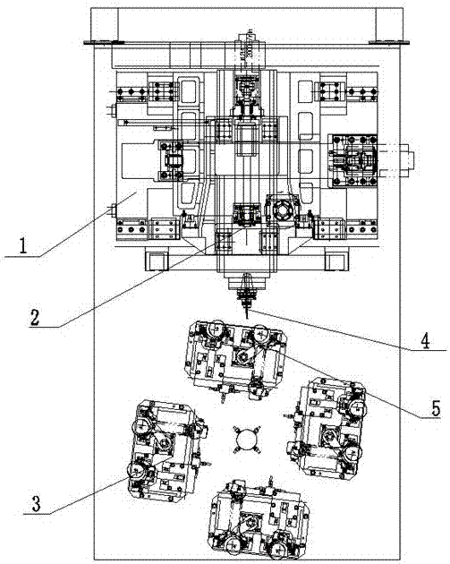
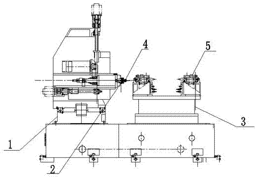
[0032] As a preferred embodiment of the present invention, with reference to the attached figure 1 and 2 , this example discloses:

[0033] Connecting rod oil hole orifice surface chamfering processing equipment, including a horizontal three-coordinate drive mechanism 1, a servo spindle drive mechanism 2 and an indexing table 3, and the servo spindle drive mechanism 2 is set on the horizontal three-coordinate drive mechanism 1 , the horizontal three-coordinate drive mechanism 1 drives the servo spindle drive mechanism 2 to move, the end of the servo spindle drive mechanism 2 is fixed with a milling cutter handle 4, and a milling cutter is fixed on the milling cutter handle 4, and the indexing table A hydraulic clamp 5 is installed on the 3, and the hydraulic clamp 5 is used to fix the connecting rod. The indexing table 3 is located at the front end of the servo spindle drive mechanism 2. By adopting the chamfering processing technology of the curved surface of the connecting...

Embodiment 2

[0035] As another preferred embodiment of the present invention, with reference to the attached figure 1 and 2 , this example discloses:

[0036] Connecting rod oil hole orifice surface chamfering processing equipment, including a horizontal three-coordinate drive mechanism 1, a servo spindle drive mechanism 2 and an indexing table 3, and the servo spindle drive mechanism 2 is set on the horizontal three-coordinate drive mechanism 1 , the horizontal three-coordinate drive mechanism 1 drives the servo spindle drive mechanism 2 to move, the end of the servo spindle drive mechanism 2 is fixed with a milling cutter handle 4, and a milling cutter is fixed on the milling cutter handle 4, and the indexing table A hydraulic clamp 5 is installed on the 3, and the hydraulic clamp 5 is used to fix the connecting rod. The indexing table 3 is located at the front end of the servo spindle drive mechanism 2. The milling tool holder 4 is a heat-expanding tool holder; the tool holder interfa...

Embodiment 3

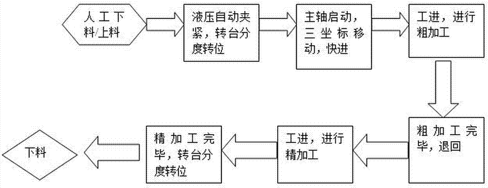
[0038] As another preferred embodiment of the present invention, with reference to the attached image 3 , this example discloses:

[0039] The method for chamfering the curved surface of the oil hole of the connecting rod comprises the following steps:

[0040] A. Establish a mathematical model according to the positioning hole coordinates of the oil hole, the processing hole coordinates and the processing hole size data, and simulate the established mathematical model through software to determine whether the established mathematical model meets the process requirements;

[0041] B. Analyze the mathematical model that meets the process requirements, convert the established mathematical model into a processing program, input the converted processing program into the horizontal three-coordinate drive mechanism 1 system, convert it into an executable program, and execute the program to make the horizontal The three-coordinate drive mechanism 1 moves according to the mathemat...


PUM


Abstract

The invention discloses chamfering machining equipment and a chamfering machining method for curved surfaces of orifices of oil holes of connecting rods, and relates to the field of machining technologies for connecting rods of engines. The chamfering machining equipment comprises a horizontal three-coordinate driving mechanism, a servo spindle driving mechanism and an indexing worktable. The servo spindle driving mechanism is arranged on the horizontal three-coordinate driving mechanism and can be driven by the horizontal three-coordinate driving mechanism to move, a milling cutter shank is arranged at an end of the servo spindle driving mechanism, and a milling cutter is fixed onto the milling cutter shank. The chamfering machining equipment and the chamfering machining method for the curved surfaces of the orifices of the oil holes of the connecting rods have the advantages that the chamfering efficiency and the precision of the profile tolerance of the machined curved surfaces can be improved, and the chamfering consistency and the surface roughness can be enhanced.

Description

technical field [0001] The invention relates to the technical field of engine connecting rod processing, in particular to a device and method for chamfering curved surface of an oil hole orifice of a connecting rod of a diesel engine. Background technique [0002] The machining of holes and shafts must have the chamfering process of the shaft head and the orifice, especially the chamfering of the orifice, which has different technical requirements due to its different functions and functions. The orifice chamfering process is often considered as an auxiliary process and is ignored by process designers, resulting in the research on the chamfering process being stopped for a long time. In many machining factories, the fitter correction is used to replace the chamfering process. Due to the lack of attention to cutting tools and process methods, the processing efficiency is reduced or it is difficult to complete the processing content of the entire process. [0003] The diamet...

Claims


Application Information

Patent Timeline
Patent Type & Authority Applications(China)
IPC IPC(8): B23C3/02
CPCB23C3/02
Inventor 黄建明王立川李红珠
Owner 四川普什宁江机床有限公司
Why Eureka
Try Eureka