Steel rail heat treatment device and heat treatment method
A heat treatment device and rail technology, applied in heat treatment furnaces, heat treatment equipment, furnaces, etc., can solve the problems of complicated operation and complex structure, and achieve the effects of convenient use, reasonable structure and suitable cooling speed.
- Summary
- Abstract
- Description
- Claims
- Application Information
AI Technical Summary
Problems solved by technology
Method used
Image
Examples
Embodiment 2
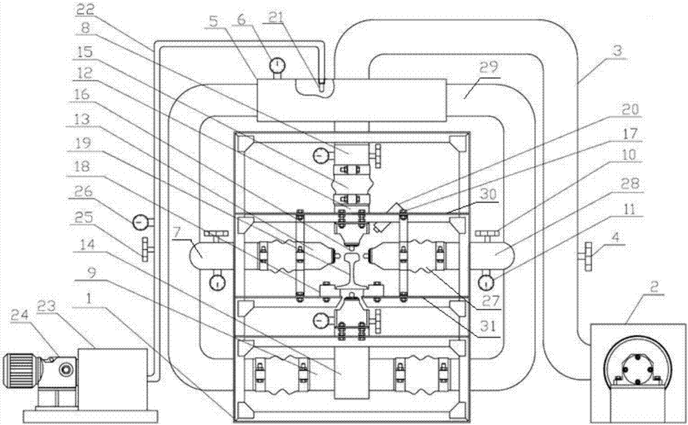
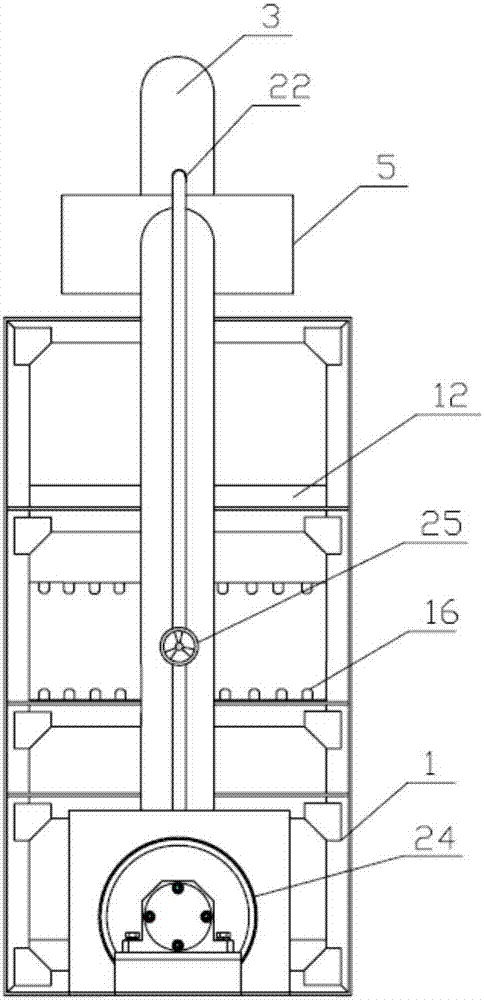
[0040] The second embodiment is different from the first embodiment: the diameter of the high-temperature atomizing nozzle 21 is 3mm, the aperture of the nozzle in the first nozzle 16 is 8mm, the distance between adjacent nozzles is 20mm, and the nozzles of the first nozzle 16 of the upper and lower air boxes The distance from the surface of the rail 19 is 30 mm, and the vertical distance between the center line of the nozzles of the first nozzles 16 of the left and right wind boxes and the rail head plane is 10 mm.
[0041] Turn on the air compressor 2, and adjust the main control valve 4 and the sub-control valve 10 to control the wind pressure of the stabilized wind box 5 to 25KPa, the wind pressure in the left and right wind boxes to 15KPa, the wind pressure in the upper wind box 12 to 16KPa, and the lower wind box 14 The pressure is 15KPa, and the air compressor 2 is turned off. Use mechanical clamps to place the rail 19 in austenite state on the stage 18, after air cooling ...
Embodiment 3
[0042] Embodiment 3 is different from Embodiment 1: the diameter of the high-temperature atomization nozzle 21 is 1.5mm, the aperture of the nozzle in the first nozzle 16 is 5mm, the distance between adjacent nozzles is 15mm, and the diameter of the first nozzle 16 of the upper and lower air boxes The distance between the nozzle and the surface of the rail 19 is 40 mm, and the vertical distance between the center line of the nozzle of the first nozzle 16 of the left and right wind boxes and the rail head plane is 12 mm.
[0043] Turn on the air compressor 2, by adjusting the main control valve 4 and the sub-control valve 10, the wind pressure of the stabilized wind box 5 is controlled to 40KPa, the wind pressure in the left and right wind boxes is 25KPa, the wind pressure in the upper wind box 12 is 30KPa, and the wind pressure in the lower wind box 14. The pressure is 20KPa, and the air compressor 2 is turned off. Use mechanical clamps to place the rail 19 in austenite state on ...
Embodiment 4
[0044] Embodiment 4 is different from embodiment 1: the diameter of the high-temperature atomizing nozzle 21 is 2mm, the aperture of the nozzle in the first nozzle 16 is 7mm, the distance between adjacent nozzles is 30mm, and the nozzles of the first nozzle 16 of the upper and lower air boxes The distance from the surface of the rail 19 is 20 mm, and the vertical distance between the center line of the nozzles of the first nozzles 16 of the left and right wind boxes and the rail head plane is 13 mm.
[0045] Turn on the air compressor 2, by adjusting the main control valve 4 and the sub-control valve 10, the wind pressure of the stabilized wind box 5 is controlled to 40KPa, the wind pressure in the left and right wind boxes is 30KPa, the wind pressure in the upper wind box 12 is 25KPa, and the wind pressure in the lower wind box 14. The pressure is 25KPa, and the air compressor 2 is turned off. Use mechanical clamps to place the rail 19 in austenite state on the loading table 18....
PUM
| Property | Measurement | Unit |
|---|---|---|
| diameter | aaaaa | aaaaa |
| length | aaaaa | aaaaa |
Abstract
Description
Claims
Application Information
 - R&D
- Intellectual Property
- Life Sciences
- Materials
- Tech Scout
- Unparalleled Data Quality
- Higher Quality Content
- 60% Fewer Hallucinations
Browse by: Latest US Patents, China's latest patents, Technical Efficacy Thesaurus, Application Domain, Technology Topic, Popular Technical Reports.
© 2025 PatSnap. All rights reserved.Legal|Privacy policy|Modern Slavery Act Transparency Statement|Sitemap|About US| Contact US: help@patsnap.com


