Check patentability & draft patents in minutes with Patsnap Eureka AI!

Device for mixed injection of fiber airflows

A technology of mixed spraying and air flow, which is applied in the field of fiber textiles, can solve the problems of heavy conveying air duct, flying flowers, poor mixing degree, etc., and achieve the effects of saving manpower and working hours, simplifying cleaning work, and improving product quality

Inactive Publication Date: 2017-09-05
徐家潼
View PDF0 Cites 1 Cited by
  • Summary
  • Abstract
  • Description
  • Claims
  • Application Information

AI Technical Summary

Problems solved by technology

[0006] 1. When the fibers of thin and short materials or other lighter materials (such as down) are mixed, these materials are not close to the drafting area of ​​the melt-blown fibers. In this case, let the melt-blown fibers be mixed into If the material is bonded and wound, serious flying flowers will appear;
[0007] 2. When thicker fibers are mixed in, these fibers are too close to the spinneret, and the meltblown fibers will roll on the thick fibers. In this way, on the one hand, the mixing degree of the two fibers is poor, and on the other hand On the one hand, the melt-blown fibers are easy to stick together to cause parallel threads, which affects the fineness of the melt-blown fibers, resulting in thickening or even bonding of the melt-blown fibers;
[0008] 3. When the distance between the mixing nozzle and the spinneret is relatively close, and it is relatively fixed within the drafting area, each time the spinneret is cleaned, the conveying air duct must be removed first, and then the spinneret cover, and finally The spinneret can only be removed for cleaning, which is time-consuming and laborious
And it is easy to damage the spinneret or the feeding air duct during the disassembly process. In addition, because the feeding air duct is heavy, at least four people need to cooperate to complete the disassembly work, which is very inconvenient;
[0009] 4. Since the position of the mixing and spraying device is fixed, it is impossible to adjust the position where the melt blown fiber and the mixed fiber meet and entangle according to different types of mixed fibers, and it is impossible to achieve the best mixing effect

Method used


Image

  • Device for mixed injection of fiber airflows
  • Device for mixed injection of fiber airflows

Examples


Embodiment Construction

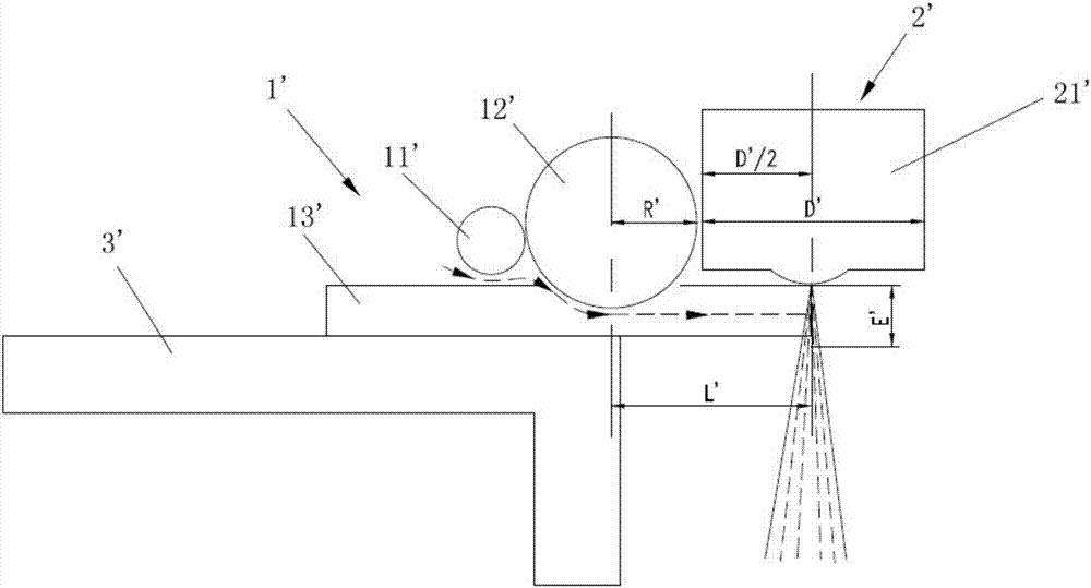
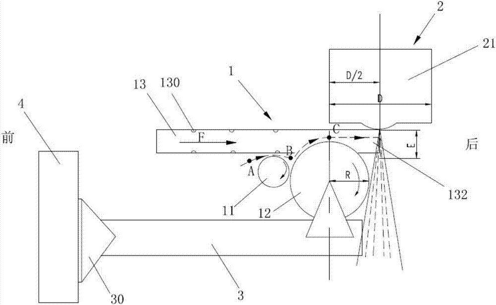
[0024] Such as figure 2 As shown, the fiber air flow mixing spraying device of the preferred embodiment of the present invention includes a supply device 1 for fiber materials to be mixed, a melt blowing device 2 , and a support 3 .

[0025] The fiber material supply device 1 to be mixed includes a first roller (doffer) 11 , a second roller (cylinder) 12 , and a conveying air duct 13 . The fiber material supply device 1 to be mixed is installed on the support 3, and the first roller 11 and the second roller 12 can rotate around their respective central axes relative to the support 3, and the rotation direction of both is the same. The diameter of the first roller 11 is smaller than that of the second roller 12 , the two are close to each other but not in contact with each other, and are arranged side by side under the conveying air duct 13 .

[0026] The feeding air duct 13 is composed of four sides, up, down, left, and right, forming a material inlet 131 and a material outl...


PUM


Abstract

The invention provides a device for mixed injection of fiber airflows. The device comprises a to-be-mixed fiber material supply device and a melt-blow device, wherein the to-be-mixed fiber material supply device comprises a first roll, a second roll and a transportation air flue; the first roll and the second roll are arranged in parallel along the longitudinal direction of the transportation air flue; a notch is formed in the transportation air flue; the second roll partially extends into the transportation air flue from the notch, so as to bring a to-be-mixed fiber material into the transportation air flue; the melt-blow device comprises a spinneret die head; the spinneret die head comprises a spinneret plate and a spinneret plate cover; along the longitudinal direction of the transportation air flue, the first roll, the second roll and the spinneret die head are arranged in sequence; the first roll and the second roll are located below the transportation air flue; and the spinneret die head is located above the transportation air flue. By adoption of the device for mixed injection of fiber airflows, the effective stroke of the to-be-mixed fiber material in the air flue is greatly shortened, the mixing uniformness of the to-be-mixed fiber material and melt-blow fiber is effectively improved, and the finished product quality is improved.

Description

technical field [0001] The invention relates to the field of fiber weaving, in particular to a fiber airflow mixing and spraying device. Background technique [0002] The melt-blown nonwoven process refers to the use of high-speed hot air to draw the thin stream of polymer melt extruded from the spinneret hole of the die, thereby forming ultra-fine fibers and spraying them on the collection device, and then relying on self-adhesion to form Become a non-woven fabric. At present, melt blown technology has become a relatively mature fiber web production process in the field of non-woven fabrics and cotton wool production. Its production process is roughly as follows: polymer feeding→melt extrusion→fiber formation→fiber cold zone→web forming→ Reinforced into cloth. [0003] If it is necessary to mix other fibers into the melt-blown fiber, it is necessary to mix the chopped fiber material into the melt-blown fiber through a special device. This special device is called a fiber ...

Claims


Application Information

Patent Timeline
Patent Type & Authority Applications(China)
IPC IPC(8): D04H1/4382D04H1/56D04H1/732
CPCD04H1/4382D04H1/56D04H1/732
Inventor 徐家潼
Owner 徐家潼
Features
  • R&D
  • Intellectual Property
  • Life Sciences
  • Materials
  • Tech Scout
  • Unparalleled Data Quality
  • Higher Quality Content
  • 60% Fewer Hallucinations
Learn More