
a ranging system

A technology of ranging system and circuit, applied in the field of ranging system, can solve the problems of poor ranging accuracy, high cost, complicated circuit, etc., and achieve the effects of easy identification and collection, high cost, and high signal-to-noise ratio.

Active Publication Date: 2019-09-10
KEENON ROBOTICS CO LTD
View PDF4 Cites 0 Cited by
  • Summary
  • Abstract
  • Description
  • Claims
  • Application Information

AI Technical Summary

Problems solved by technology

[0003] The technical problem to be solved by the present invention is to provide a ranging system to solve the problems of poor ranging accuracy, complex circuits, and high cost in the prior art

Method used


Image

  • a ranging system
  • a ranging system
  • a ranging system

Examples


Embodiment

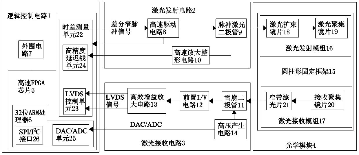
[0031] Such as figure 1 As shown, a distance measuring system provided by the present invention has the characteristics of low cost, simplified circuit and high confidentiality. The traditional TOF distance measuring needs a transmitting circuit, a receiving circuit, a time difference measuring circuit and a digital control circuit, so the system circuit The cost is high, and the debugging is complicated. All the time difference signals of the present invention are completed by the high-speed FPGA of the logic control circuit, and utilize the high-speed FPGA to collect the initial signal of the transmitting circuit circuit, and the LVDS unit collects the differential signal from the receiving end, and the LVDS unit collects the signal from the For the differential signal at the receiving end, the received signal outputs a STOP signal after passing through the LVDS unit, which saves the time difference measurement circuit in the prior art as a whole, saves the cost, and simplifi...


PUM


Abstract

The invention discloses an ultra high speed precision ranging system, and solves the problems of low ranging precision, complicated circuit and high cost in the prior art. The ultra high speed precision ranging system includes a logic control circuit, a laser emitting circuit, a laser receiving circuit and an optical module. The logic control circuit comprises a high-speed FPGA chip which is mainly for logic control and is embedded with a 32-bit ARM processor and a time difference measuring unit, and a peripheral circuit. The laser emitting circuit includes a high-speed driving circuit, a pulsed laser diode and a high-speed amplifying and shaping circuit. The laser receiving circuit includes an avalanche diode, a front I / V circuit, a high gain amplifying circuit and a high voltage generating circuit. The optical module comprises a cylindrical fixing frame, a laser emitting module and a laser receiving module. The ultra high speed precision ranging system has the characteristics of high speed driving, adjustable laser emission peak power, high signal to noise ratio, low cost, simplified circuit, high confidentiality, high ranging accuracy and speed, and human eye safety of output laser.

Description

technical field [0001] The invention relates to a ranging system. Background technique [0002] With the development of laser technology, the use of laser distance measurement in the field of distance measurement has the advantages of high speed, high efficiency and accurate measurement, and the laser distance measurement system has become an indispensable measurement equipment in the market. However, the measurement accuracy and measurement frequency of the traditional laser ranging are not high enough, and the circuit of the traditional laser ranging system is relatively complicated and the cost is high. Therefore, designing a ranging system to solve the above-mentioned problems existing in traditional laser ranging has become a technical problem to be solved urgently by those skilled in the art. Contents of the invention [0003] The technical problem to be solved by the present invention is to provide a ranging system to solve the problems of poor ranging accuracy, co...

Claims


Application Information

Patent Timeline
Patent Type & Authority Patents(China)
IPC IPC(8): G01S17/10G01S7/484G01S7/486
Inventor 郭忠华冉银春孙家强余江孙长征
Owner KEENON ROBOTICS CO LTD
Learn More