
Power semiconductor device and manufacturing method thereof

A technology for power semiconductors and manufacturing methods, which is applied in semiconductor/solid-state device manufacturing, semiconductor devices, electrical components, etc., and can solve the problems of increasing on-resistance Rdon, increasing chip area, and insufficient area.

Pending Publication Date: 2017-09-05
深圳深爱半导体股份有限公司
View PDF7 Cites 2 Cited by
  • Summary
  • Abstract
  • Description
  • Claims
  • Application Information

AI Technical Summary

Problems solved by technology

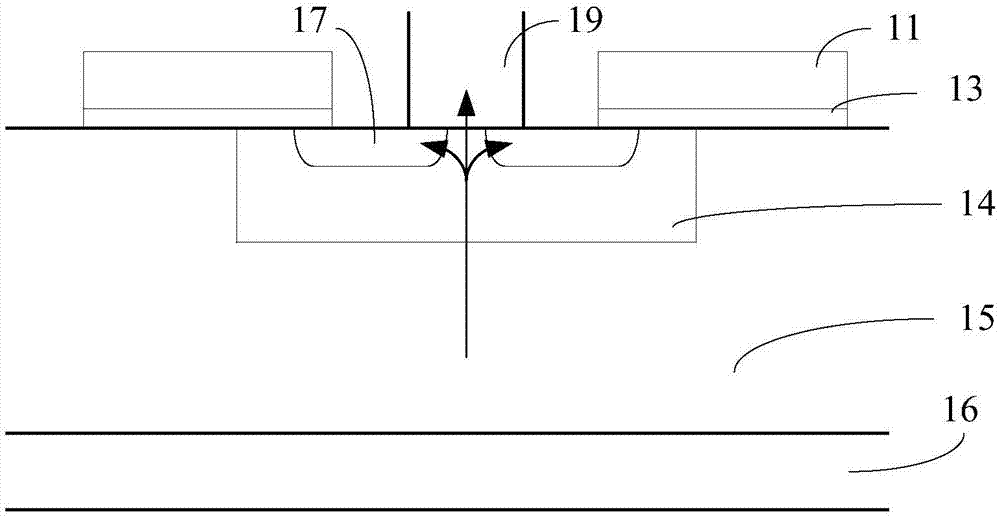
[0004] 1. Although increasing the implantation dose of the P well can increase the avalanche tolerance, it will increase the turn-on voltage VTH, and more seriously, it will increase the on-resistance Rdon, which will increase the temperature rise of the device, thereby reducing the reliability of the device
[0005] 2. P+ injection after N+ injection will also increase the turn-on voltage VTH, and increase the on-resistance Rdon, which will increase the temperature rise of the device, thereby reducing the reliability of the device
The reason is that the impurity boron ions implanted during this P+ implantation are close to the channel of the device, and the boron ions will diffuse into the channel in the subsequent diffusion process, thereby increasing the turn-on voltage VTH and increasing the on-resistance Rdon
[0006] 3. Increasing the number of cells will increase the area of ​​the chip, thereby increasing the manufacturing cost
[0007] 4. Although P+ implantation after contact hole etching will improve the device burnout caused by poor contact of individual cells in the device, due to the limited size of the contact hole in general, the area of ​​P-type impurities implanted through the contact hole If it is not large enough, the reduction of the resistance Rb of the device body region is limited, so that the improvement of the avalanche resistance is not large enough, so this method is not efficient in improving the avalanche resistance of the device

Method used


Image

  • Power semiconductor device and manufacturing method thereof
  • Power semiconductor device and manufacturing method thereof
  • Power semiconductor device and manufacturing method thereof

Examples


Embodiment Construction

[0031] In order to facilitate the understanding of the present invention, the present invention will be described more fully below with reference to the associated drawings. A preferred embodiment of the invention is shown in the drawings. However, the present invention can be embodied in many different forms and is not limited to the embodiments described herein. Rather, these embodiments are provided so that the disclosure of the present invention will be thorough and complete.

[0032] Unless otherwise defined, all technical and scientific terms used herein have the same meaning as commonly understood by one of ordinary skill in the technical field of the invention. The terms used herein in the description of the present invention are for the purpose of describing specific embodiments only, and are not intended to limit the present invention. As used herein, the term "and / or" includes any and all combinations of one or more of the associated listed items.

[0033] The se...


PUM


Abstract

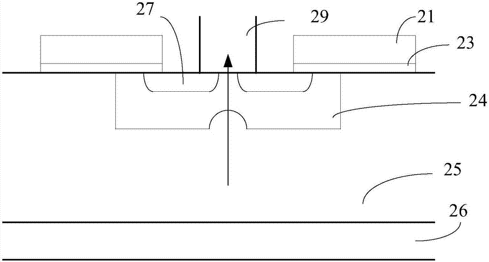
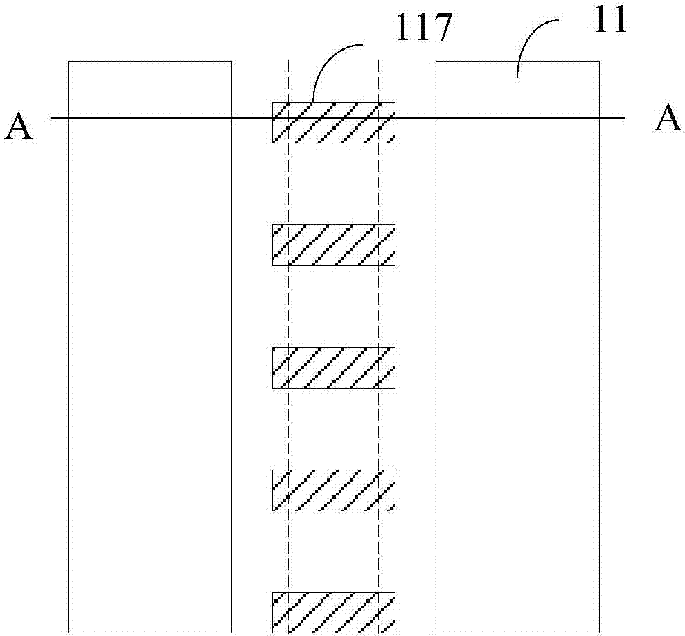
The invention relates to a power semiconductor device and a manufacturing method thereof. The manufacturing method comprises the a step of well injection, and is characterized in that an injection blocking layer in the step of well injection comprises a strip-shaped injection blocking structure located between two adjacent grid electrodes, the bottom of a well region below the injection blocking structure is enabled to form a recess sinking into the well region upward after well injection and diffusion, the extending direction of the strip-shaped injection blocking structure is perpendicular to the spacing direction of the two adjacent grid electrodes, and the width of the injection blocking structure is less than the width of a metal interconnecting wire connected with a source region at the source region connecting part. When the power semiconductor device is turned off in an inductive load circuit, hole current flowing from the recess is short in path to source metal, and the hole current can directly get into the source metal, so that the possibility of getting into the source region is reduced, a parasitic NPN transistor is enabled to be difficult to open, and thus the avalanche tolerance of the device is increased.

Description

technical field [0001] The invention relates to the field of semiconductor manufacturing, in particular to a power semiconductor device and a method for manufacturing the power semiconductor device. Background technique [0002] Due to the particularity of the use environment and conditions of use, modern electronic circuits have higher and higher requirements for the reliability of power semiconductor devices. Power semiconductor devices (power VDMOS, power IGBT, etc.) are often connected to inductive load circuits due to the needs of use. When the device is turned off, the inductance on the inductive load can generate a voltage twice the power supply voltage applied to the load circuit, which is added between the drain and source of the device, causing the drain and source of the device to withstand a large current impact. When the drain voltage increases and cannot be pinched off, the device enters the avalanche region. At this time, the drain-body diode will generate cu...

Claims


Application Information

Patent Timeline
IPC IPC(8): H01L29/06H01L29/417H01L21/336H01L29/739H01L29/78
CPCH01L29/0688H01L29/41725H01L29/66325H01L29/66712H01L29/7393H01L29/7802
Inventor 李学会
Owner 深圳深爱半导体股份有限公司
Learn More