Pipeline inner wall bionic groove surface machining device and machining method thereof

A surface processing and pipeline technology, which is applied in the field of bionic groove surface processing devices on the inner wall of pipelines, can solve the problems of reducing oil and gas transportation resistance, not obvious economic benefits, large turbulent flow resistance, etc., to avoid bending deformation and torsional deformation, structure The effect of compact design and guaranteed operation quality

Active Publication Date: 2017-09-08
ZHEJIANG UNIV OF TECH
View PDF7 Cites 15 Cited by
  • Summary
  • Abstract
  • Description
  • Claims
  • Application Information

AI Technical Summary

Problems solved by technology

Coating drag reduction technology is to coat a layer of drag reduction coating on the inner surface of the pipeline, but there is a large turbulent pulsation resistance, and the drag reduction ability is very weak
The drag reduction of drag reducer is simpler than that of coating, but the drag reducer is consumed quickly and needs to be replenished continuously, especially for pipelines that need to be tr

Method used


Image

  • Pipeline inner wall bionic groove surface machining device and machining method thereof
  • Pipeline inner wall bionic groove surface machining device and machining method thereof
  • Pipeline inner wall bionic groove surface machining device and machining method thereof

Examples


Embodiment 1

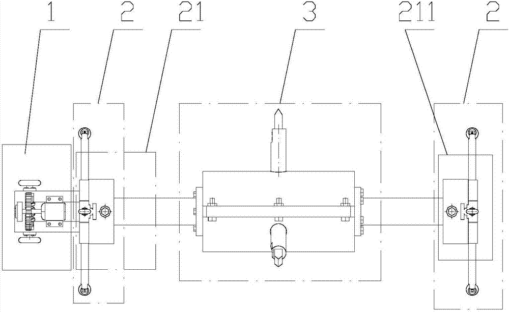
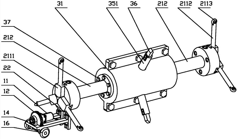
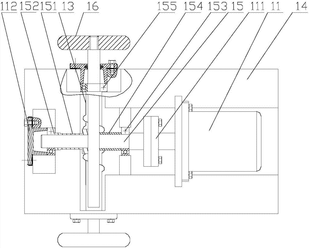
[0035] Embodiment 1 A bionic groove surface processing device for the inner wall of a pipeline according to the present invention includes a driving mechanism 1 for providing a driving force, a walking mechanism 2 for supporting the inner wall of the pipeline, and a driving mechanism 2 for processing the inner wall of the pipeline. The processing mechanism 3 and the controller for processing the bionic groove, the driving mechanism 1 is installed on the running mechanism 2 through bolts; the processing mechanism 3 is fixedly connected with the running mechanism 2 through bolts; the driving mechanism 1 and the processing mechanism 3 are both corresponding to the controller The control terminal is electrically connected; the driving mechanism 1 includes a driving motor 11, a worm wheel 12, a worm screw 13, a support frame 14, a transmission shaft 15 and a roller 16, and the driving motor 11 is installed vertically, and is fixed on the On the support frame 14; the output shaft of ...

Embodiment 2

[0045] Embodiment 2 According to the processing method of a bionic groove surface processing device for the inner wall of a pipeline described in Embodiment 1, the processing method includes the following steps:

[0046] 1) According to the diameter of the pipe to be processed, adjust the front and rear traveling mechanisms so that the three moving claws move at the same time to drive the three support rods to extend radially until the rollers can just touch the inner wall of the pipe to ensure that the entire processing device enters the pipe Part of the internal operation is balanced to ensure its stability;

[0047] 2) Adjust the bolts of the bracket under the front travel unit to move the drive mechanism radially until the rollers installed at both ends of the worm touch the inner wall of the pipeline;

[0048] 3) Place the bionic groove surface processing device on the inner wall of the pipeline completely in the pipeline to be processed to ensure its stability;

[0049]...


PUM


Abstract

The invention provides a pipeline inner wall bionic groove surface machining device and a machining method thereof. The device comprises a drive mechanism used for providing drive force, a traveling mechanism used for supporting the inner wall face of a pipeline, a machining mechanism used for machining a bionic groove in the inner wall of the machined pipeline, and a controller. The drive mechanism is installed on the traveling mechanism through bolts. The machining mechanism is fixedly connected with the traveling mechanism through bolts. The drive mechanism and the machining mechanism are electrically connected with corresponding control ends of the controller. The method comprises the steps that according to the diameter of the pipeline needing to be machined, a front and back traveling unit is adjusted in a rotating manner, after the machining mechanism is moved to the position, to be machined, on the inner wall of the pipeline, the traveling unit stops moving and presses the inner wall of the pipeline, the cutter position of the machining mechanism is adjusted, and the groove in the inner wall of the pipeline begins to be machined. The device has the beneficial effects that tangential counter force borne by three tools in the cutting machining process can be offset, thus, bending deformation and torsional deformation are avoided, and meanwhile the device is high in precision, simple in structure and easy to operate.

Description

technical field [0001] The invention relates to a surface processing device and method for bionic grooves on the inner wall of a pipeline. Background technique [0002] The pipeline transportation of fuels such as oil and natural gas will generate relatively large transportation resistance, thereby reducing the transportation efficiency. At present, coating drag reduction and adding polymer drag reducer are mainly applied to a small number of pipelines. Coating drag reduction technology is to coat a layer of drag reduction coating on the inner surface of the pipeline, but there is a large turbulent pulsation resistance, and the drag reduction ability is very weak. The drag reduction of drag reducer is simpler than that of coating, but the drag reducer is consumed quickly and needs to be replenished continuously, especially for pipelines that need to be transported for a long time, because a large amount of drag reducer is required, the economic benefit is not good obvious....

Claims


Application Information

Patent Timeline
IPC IPC(8): B26D3/08
CPCB26D3/08
Inventor 谷云庆刘涛牟介刚郑水华吴登昊周佩剑王曼牟成琪张文奇杜魏媛张冯烨
Owner ZHEJIANG UNIV OF TECH
Why Eureka
Try Eureka