
Power steering device of intelligent computing motor target torque

A technology of electric power steering and target torque, which is applied in the direction of electric steering mechanism, power steering mechanism, mechanical steering gear, etc., and can solve the problems such as damage to the steering nut of the gear fan shaft, difficulty in electromechanical matching, and difficulty in system matching , to achieve the effect of improving reliability, reducing stress and enhancing connection strength

Inactive Publication Date: 2017-09-08
CHINA NORTH VEHICLE RES INST
View PDF5 Cites 3 Cited by
  • Summary
  • Abstract
  • Description
  • Claims
  • Application Information

AI Technical Summary

Problems solved by technology

Due to practical factors such as the large load on the steering axle of heavy vehicles (generally more than 4 tons) and the singleness of the layout of the power steering device (usually located in the power cabin), the use of rack and pinion steering devices or steering column steering devices cannot meet the requirements. , it is necessary to adopt a recirculating ball structure with high overall structural strength and strong impact resistance, and the current recirculating ball steering structure only exists in heavy-duty hydraulic power steering devices and has nothing to do with electric power steering systems
[0007] 2. The structural strength requirements of key components and parts are high, and the system matching is difficult
As far as the recirculating ball hydraulic power steering is concerned, its screw, gear fan shaft, housing, steering nut and other components are often damaged due to external impact loads
[0008] 3. Electromechanical matching is difficult
[0009] In addition, there are problems caused by inaccurate calculation of the motor target torque, or the inability to perform automatic calculation

Method used


Image

  • Power steering device of intelligent computing motor target torque
  • Power steering device of intelligent computing motor target torque
  • Power steering device of intelligent computing motor target torque

Examples


Embodiment Construction

[0078] The specific embodiments of the present invention will be described in detail below in conjunction with the accompanying drawings.

[0079]In this article, if there is no special explanation, when it comes to formulas, " / " means division, and "×" and "*" mean multiplication.

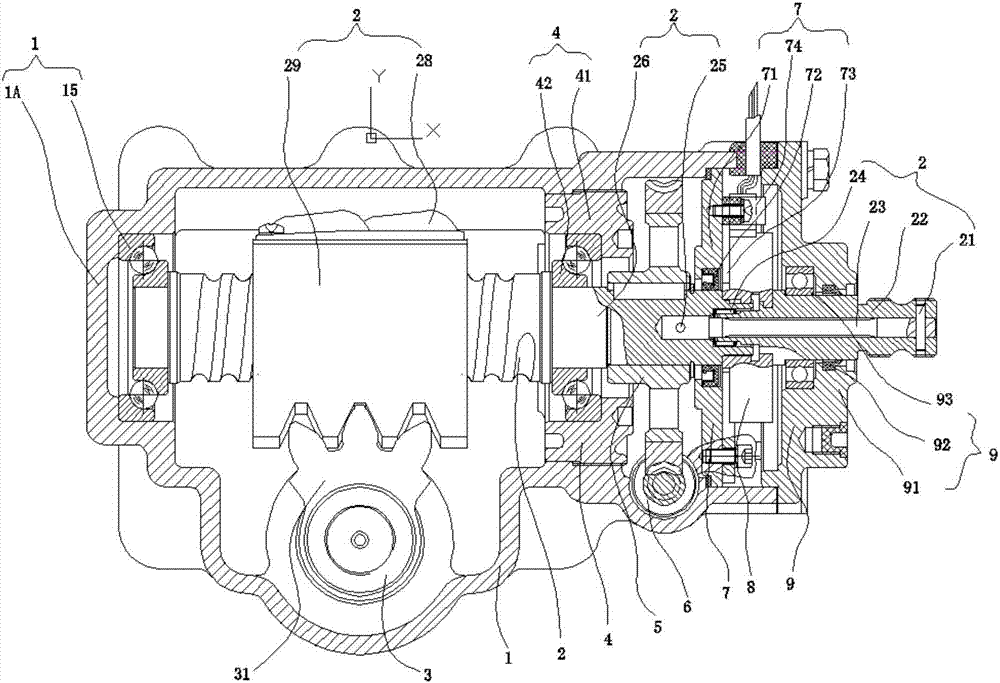
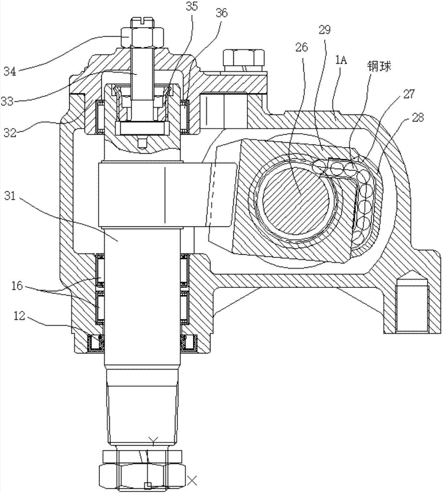
[0080] In order to solve the problems of the prior art, the present invention provides a heavy-duty recirculating ball type dual-mode electric power steering device, such as Figure 1-Figure 3 As shown, it is characterized in that it includes: housing assembly 1, input shaft and screw assembly 2, gear fan shaft assembly 3, support seat assembly 4, turbine 5, worm 6, inner end cover assembly 7, Angle torque sensor 8, outer end cover assembly 9, plum blossom connection sleeve assembly 10, motor assembly 11;

[0081] The inside of the housing assembly is horizontally provided with a cavity with one end closed and one end open. The input shaft and screw assembly 2 are installed in the cavity of the h...


PUM


Abstract

The invention provides a power steering device of an intelligent computing motor target torque. The power steering device comprises a housing assembly (1), an input and screw rod assembly (2), a gear sector shaft assembly (3), a corner torque sensor (8) and a motor assembly (11). When an input shaft is rotated forwardly or backwardly by a steering wheel, the input shaft is connected with a screw rod shaft by an elastic torsion bar and a certain angle is formed between the input shaft and the screw rod shaft, the screw rod shaft can coaxially rotate with the input shaft as the screw rod shaft and the input shaft reach an angular displacement banking limit; the corner torque sensor shaft is axially connected with the input shaft and the screw rod shaft; and the control system computes a target torque of the motor assembly via collecting an output torque value of the corner torque sensor, and drives the motor assembly to output an assisting torque via a torque control mode. The target torque of the motor assembly can be intelligently computed and the motor assembly can be driven to output the assisting torque via the torque control mode, so intelligence degree of the steering device can be improved.

Description

technical field [0001] The invention belongs to the application field of electromechanical systems and motor vehicles, and in particular relates to a heavy-duty circulating ball type dual-mode electric power steering device. Background technique [0002] From the perspective of the automobile industry, as the number of fuel vehicles continues to grow, vehicle emissions are causing more and more serious pollution to the environment. At the same time, oil, as a non-renewable energy source, is also facing the crisis of depletion. Vehicles and hybrid vehicles have become the focus of the government and society because of their advantages of energy saving and environmental protection, and have become the core development theme of today's wheeled vehicle technology. Electric power steering technology (EPS) has been widely used in domestic and foreign household vehicles due to its significant advantages such as high integration, energy saving, and maintenance-free, but it is mostly...

Claims


Application Information

Patent Timeline
IPC IPC(8): B62D5/04B62D3/08
CPCB62D3/08B62D5/0445B62D5/0463
Inventor 李玉雷强顺刘海涛张勇王成玲刘富强王东亮
Owner CHINA NORTH VEHICLE RES INST
Learn More