
Heat pump dryer system

A technology of a dryer and a heating system, applied in the field of heat pumps, can solve problems such as affecting the drying effect inside the dryer, frosting of an evaporative coil, affecting the cooling and heat absorption effect of the evaporative coil, etc., and achieve the effect of heat production. , The effect of increasing refrigerant flow, simple and effective structure

Inactive Publication Date: 2017-09-08
HEFEI VANDRA REFRIGERATION TECH
View PDF6 Cites 6 Cited by
  • Summary
  • Abstract
  • Description
  • Claims
  • Application Information

AI Technical Summary

Problems solved by technology

[0004] However, the existing domestic heat pump dryers have the following defects: 1. In the case of using a single compressor, the compression efficiency of the compressor cannot be improved to the greatest extent; 2. The air in the inner cavity of the heat pump dryer often A large amount of water vapor appears, which affects the drying effect of the entire dryer; 3. When the ambient temperature is low, frosting often occurs on the evaporating coil, which greatly affects the cooling and heat absorption effect of the evaporating coil

Method used


Image

  • Heat pump dryer system
  • Heat pump dryer system

Examples


Embodiment Construction

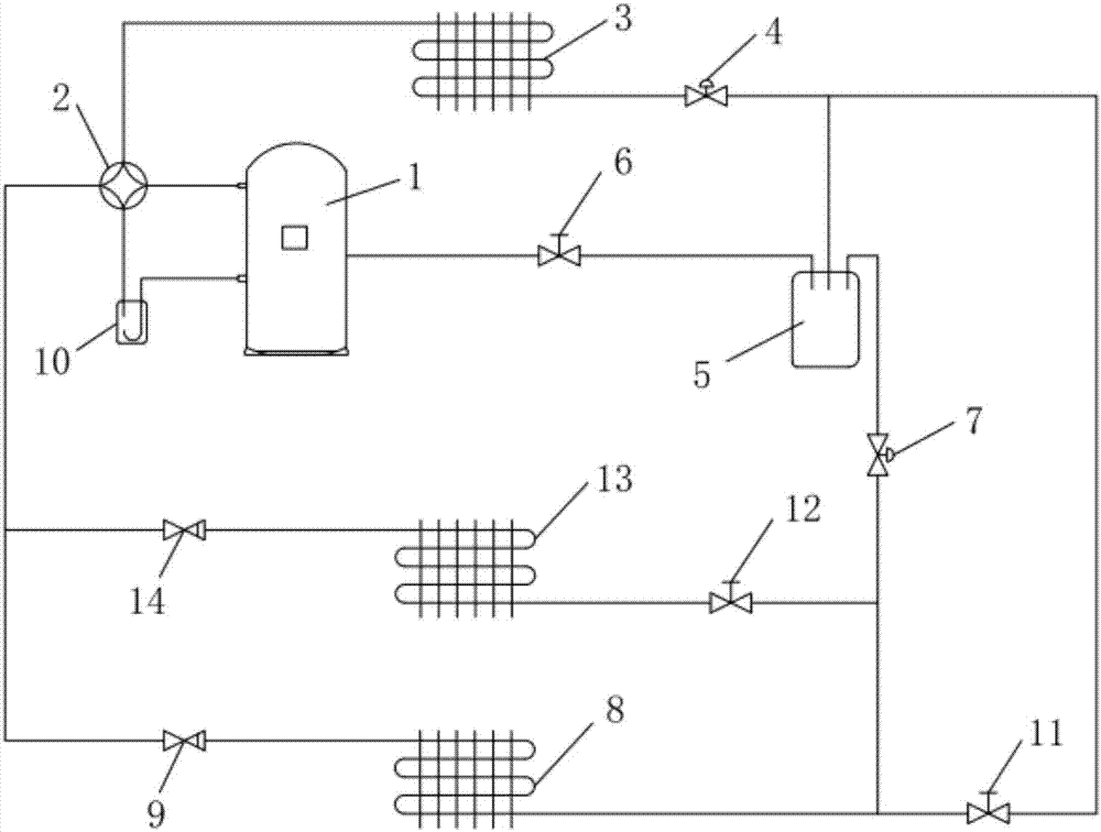
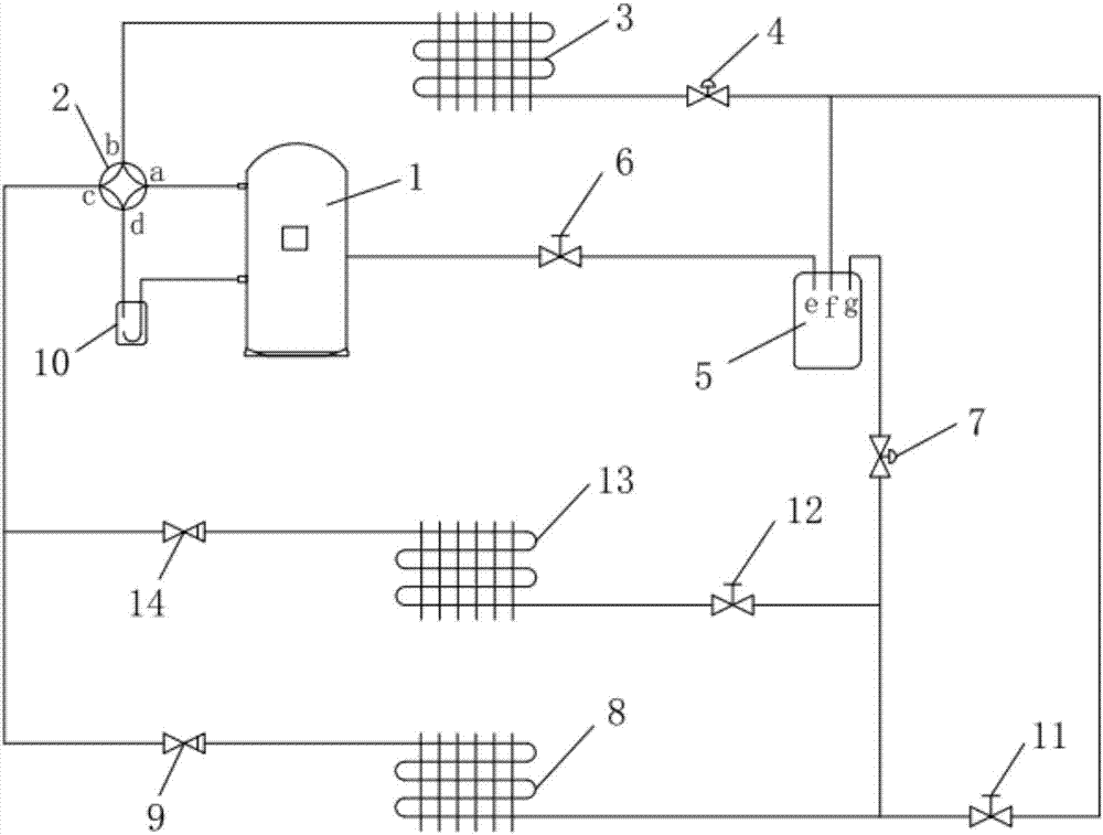
[0026] The following will clearly and completely describe the technical solutions in the embodiments of the present invention with reference to the accompanying drawings in the embodiments of the present invention. Obviously, the described embodiments are only some, not all, embodiments of the present invention. Based on the embodiments of the present invention, all other embodiments obtained by persons of ordinary skill in the art without making creative efforts belong to the protection scope of the present invention.

[0027] see Figure 1-2 , the present invention provides a technical solution:

[0028] A heat pump dryer system, including a heating system, an economizer system, a defrosting system, and a dehumidification system, wherein the heating system is used to realize heat generation by the heat pump, the economizer system is used to improve compressor efficiency, and the defrosting system It is used to enhance the defrosting ability of the system, and the dehumidifi...


PUM


Abstract

The invention discloses a heat pump dryer system. A heating system comprises an air injection enthalpy increasing compressor, a four-way reversing valve, a heating coiler, a thermostatic expansion valve, a refrigerating coiler and a gas-liquid separating device; an economizer system comprises a flash evaporator and a jetting electromagnetic valve; the dehumidification system comprises an electronic expansion valve, a dehumidification electromagnetic valve and a dehumidification coiler; a defrosting system is a singly-arranged defrosting electromagnetic valve; the flash evaporator and the electronic expansion valve are connected between the thermostatic expansion valve and the refrigerating coiler in series, the flash evaporator is arranged on the side close to the thermostatic expansion valve, and the flash evaporator is further connected to the input end of the enthalpy increasing compressor through the jetting electromagnetic valve; the dehumidification electromagnetic valve and the dehumidification coiler are connected to the two ends of the refrigerating coiler in parallel, and the dehumidification electromagnetic valve is arranged on one side close to the electronic expansion valve; and the dehumidification electromagnetic valve is connected to the two ends of the flash evaporator and the electronic expansion valve in parallel. By means of the heat pump dryer system, the compressor efficiency and the internal dehumidification and defrosting effects can be improved, the structure is simple and effective, and the heat pump dryer system is worthy of popularization.

Description

technical field [0001] The invention relates to the technical field of heat pumps, in particular to a heat pump dryer system. Background technique [0002] The traditional grain dryer is heated by a coal-fired hot blast stove. The combustion efficiency of coal and the heat exchange efficiency of flue gas heating air are low, and a large amount of heat is wasted during the conveying process of the air duct. In addition, the brick wall of the hot blast stove has poor thermal insulation performance. , so that the heat energy utilization rate of the entire drying device is very low; in the traditional grain drying production using coal-fired hot stove heating, relying on manual observation and experience to judge and control and adjust the process (controlling the temperature, adjusting the temperature), baking The quality is unstable; the entire drying process is manually operated and controlled, and the labor intensity is relatively high. [0003] In this context, the air sou...

Claims


Application Information

Patent Timeline
IPC IPC(8): F26B21/00F25B13/00F25B41/04F25B41/06F25B47/02F25B41/20F25B41/34
CPCF25B13/00F25B47/02F26B21/001F25B2313/02741F25B2347/02F25B2400/13F25B41/34F25B41/20F25B41/31Y02B30/70
Inventor 王海明
Owner HEFEI VANDRA REFRIGERATION TECH
Learn More