Protection system for hot parts of aircraft

A technology for thermal components and aircraft, which is applied in aircraft parts, air handling equipment, fuselage, etc., and can solve problems that are not conducive to the wide speed range, long-term flight of hypersonic aircraft, increase the weight of the aircraft itself, and low fuel sensible heat sink, etc. problems, to achieve the effect of improving applicability and practicability, reducing carrying capacity, and simple implementation

Active Publication Date: 2018-06-22
TSINGHUA UNIV
View PDF6 Cites 5 Cited by
  • Summary
  • Abstract
  • Description
  • Claims
  • Application Information

AI Technical Summary

Problems solved by technology

However, due to the low sensible heat sink of the fuel, the aircraft is required to carry an amount of fuel that is much greater than that required for engine combustion before take-off, which will greatly increase the weight of the aircraft itself, which is not conducive to the wide speed range and long-term flight of hypersonic aircraft.
[0004] In addition, the latent heat of vaporization of the liquid working medium can provide a heat sink that is much larger than the sensible heat. If the latent heat of vaporization of the cooling medium can be used safely and effectively, the carrying capacity of the cooling medium can be greatly reduced. However, if the cooling medium is used in the cooling channel Direct overheating and vaporization in the interior is likely to cause heat transfer deterioration and bring immeasurable losses

Method used


Image

  • Protection system for hot parts of aircraft

Examples


Embodiment Construction

[0025] Embodiments of the present invention are described in detail below, examples of which are shown in the drawings, wherein the same or similar reference numerals designate the same or similar elements or elements having the same or similar functions throughout. The embodiments described below by referring to the figures are exemplary and are intended to explain the present invention and should not be construed as limiting the present invention.

[0026] A protection system for aircraft thermal components according to an embodiment of the present invention is described below with reference to the accompanying drawings.

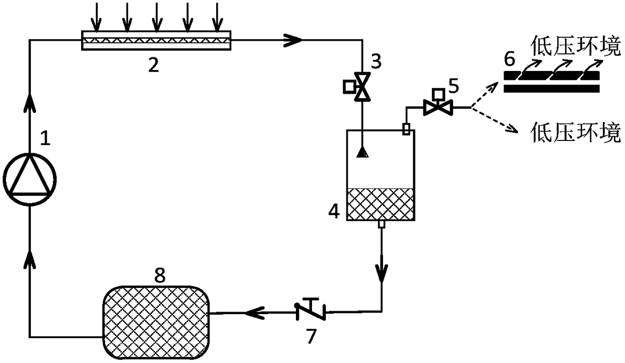
[0027] figure 1 It is a structural schematic diagram of a protection system for aircraft thermal components according to an embodiment of the present invention.

[0028] Such as figure 1 As shown, the protection system for the hot parts of the aircraft includes: a water pump 1 , a first electronic back pressure valve 3 , a flash chamber 4 , a second elec...


PUM


Abstract

The invention discloses a protective system of an aircraft thermal part. The protective system comprises a water pump for pressurizing cooling water into a cooling channel of the aircraft thermal part, a first electronic back pressure valve, a flash evaporation cavity for conducting flash evaporation on the cooling water passing through the electronic back pressure valve after heating, a second electronic back pressure valve for exhausting water vapor produced after flash evaporation to an outside low-pressure environment, and a water bag for receiving liquid left in the flash evaporation cavity after flash evaporation and flowing back under the effects of the gravity and the pressure, wherein the water vapor is guided into air film holes formed in other thermal parts when the pressure of the water vapor exceeds a first preset pressure value. The protective system utilizes a water flash evaporation mode to thermally protect the thermal part, can effectively cool the surface of the thermal part, can remarkably decrease the cooling medium carrying amount, thus decrease the vehicle body weight of a hypersonic aircraft, strengthens the task executing capability of the aircraft and is simple and easy to achieve, and the applicability and practicability of the system are improved.

Description

technical field [0001] The invention relates to the technical field of heat protection, in particular to a protection system for aircraft heat components. Background technique [0002] During the flight of a hypersonic vehicle, hot components such as the head, inlet lip, engine wall, body, etc. need to withstand high heat flux density, and due to the needs of the flight mission, the flight speed of the hypersonic vehicle Higher requirements are put forward for flight time and flight time, and passive and semi-passive cooling methods can no longer meet the cooling requirements of the aircraft during mission execution, and active thermal protection technology is required. [0003] In related technologies, the active thermal protection method mainly utilizes the single-phase sensible heat of temperature rise of the engine fuel to convectively cool the surface of the hot component. However, due to the low sensible heat sink of the fuel, the aircraft is required to carry far mor...

Claims


Application Information

Patent Timeline
Patent Type & Authority Patents(China)
IPC IPC(8): B64D13/00B64C1/38
CPCB64C1/38B64D13/006
Inventor 姜培学王超胥蕊娜祝银海欧阳小龙
Owner TSINGHUA UNIV
Why Eureka
Try Eureka