Oil-gas separator

A technology of oil and gas separator and separator, which is applied in the direction of machine/engine, engine components, mechanical equipment, etc., can solve the problems of high engine oil consumption, high crankcase pressure, complicated disassembly and assembly process, etc., to reduce oil consumption, Efficient and thorough separation to ensure the effect of separation efficiency

Active Publication Date: 2017-09-12
HENGST FILTER SYST (KUNSHAN) CO LTD
View PDF9 Cites 9 Cited by
  • Summary
  • Abstract
  • Description
  • Claims
  • Application Information

AI Technical Summary

Problems solved by technology

[0004] First, a labyrinth oil-gas separator composed of baffles is used; in order to achieve a good separation effect, the oil-gas separator needs more baffles, which takes up a lot of space and is not conducive to the miniaturization and overall layout of the engine; at the same time, the more baffles , when the engine is running at high speed, the pressure in the crankcase is high, and it is easy to make the oil return poor
[0005] Second: Filter-type oil-gas separator; it separates engine oil and gas by filtering. The separation efficiency of this kind of oil-gas separator is low. When there is a lot of oil-gas mixture to be separated, the oil-gas separation is not complete and the effect is not good.
[0006] Third: the cyclone oil-gas separator; it contains many parts, the disassembly process is complicated, the maintenance is difficult, and the applicability is poor
[0007] At the same time, these conventional oil-gas separators that are constructed or composed of baffles, cyclones, etc. cannot control the flow direction of the separated gas, and require an external one-way valve to control the flow direction of the separated gas, and the cost is relatively high
[0008] Moreover, when the blow-by gas of the engine increases in these conventional oil-gas separators, the pressure difference increases sharply, and the separation efficiency further decreases, resulting in high engine oil consumption

Method used


Image

  • Oil-gas separator
  • Oil-gas separator
  • Oil-gas separator

Examples


Embodiment

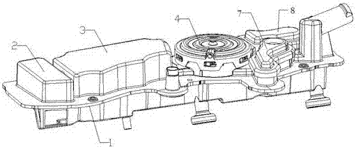
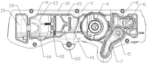
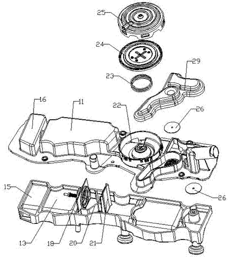
[0035] Crankcase blow-by gas enters from the entrance of the blow-by gas gathering chamber 2, and the gas passing through the speed-increasing channel 12 impacts on the arc-shaped baffle 14, and the relatively large oil particles in the gas adhere to the arc-shaped baffle 14, and finally due to the action of gravity The gas falls in the coarse separation chamber 13 , while the gas that separates larger oil particles overflows from the gaps 17 on both sides of the arc-shaped baffle 14 , and then enters the fine separation chamber 19 through the felt valve 18 .

[0036] When the blow-by gas of the engine is small, the pressure difference between the two ends of the felt valve 18 is small, and the felt valve 18 is in a closed state at this time, and all the gas passes through the felt valve body 31. Blocked by the body 31, it gradually accumulates in the felt valve body 31, and finally drips into the cavity of the separator body 1 due to the effect of gravity. The flow velocity o...


PUM


Abstract

The invention relates to an oil-gas separator, and belongs to the technical field of automobile engines. The oil-gas separator comprises a separator body, a moving gas gathering chamber, an oil-gas separating part, a pressure adjusting valve, a small load one-way valve, a large load one-way valve, a small load channel and a large load channel; the moving gas gathering chamber is arranged on the left portion of the separator body, and is connected with the oil-gas separating part, the pressure adjusting valve is arranged on the rear side of the oil-gas separating part, the small load channel and the large load channel are formed in the rear side of the pressure adjusting valve, the small load channel is provided with the small load one-way valve, and the large load channel is provided with the large load one-way valve. The one-way valves are directly integrated in the separator body, the oil-gas separating part of the special structure is arranged, oil and gas can be efficiently and thoroughly separated, the separating efficiency is improved, meanwhile,, the structure of the oil-gas separator is simplified, the manufacturing cost of the separator is reduced, the oil-gas separating efficiency is ensured, meanwhile, it is ensured that the pressure difference of the whole oil-gas separator is within the reasonable range, and the engine oil consumption is reduced.

Description

technical field [0001] The invention belongs to the technical field of automobile engines, and in particular relates to an oil-gas separator. Background technique [0002] During the operation of the automobile engine, combustible mixed gas and exhaust gas will enter the crankcase, dissolve in the oil, dilute the oil, and deteriorate the performance. Pollutants such as particles contained in the exhaust gas will mix with the oil, causing the oil to deteriorate and corrode parts; At the same time, the engine generates heat, the oil volatilizes, and the internal pressure of the crankcase increases. The oil will leak from the crankcase oil seal and other places. The loss of engine oil will cause excessive oil consumption, and the steam generated by the volatilization of engine oil will also pollute the atmosphere. Therefore, the engine uses a crankcase ventilation system to remove crankcase blow-by, prevent oil deterioration, reduce oil consumption, and reduce emissions. [00...

Claims


Application Information

Patent Timeline
Patent Type & Authority Applications(China)
IPC IPC(8): F01M13/04
CPCF01M13/04
Inventor 西蒙·贝格尔韩小伟尹紫恒
Owner HENGST FILTER SYST (KUNSHAN) CO LTD
Why Eureka
Try Eureka