Vehicle exhaust gas purifier

A technology for purifying automobile exhaust and exhaust gas is applied in exhaust treatment, exhaust devices, machines/engines, etc., to achieve the effects of good purification, low production cost and simple production conditions

Inactive Publication Date: 2017-09-12
SUZHOU BOHAN ENVIRONMENTAL PROTECTION TECH
View PDF4 Cites 3 Cited by
  • Summary
  • Abstract
  • Description
  • Claims
  • Application Information

AI Technical Summary

Problems solved by technology

That is to say, there is currently a lack of a vehicle exhaust purification device with ideal effect and wide application.

Method used


Image

  • Vehicle exhaust gas purifier

Examples


Embodiment 1

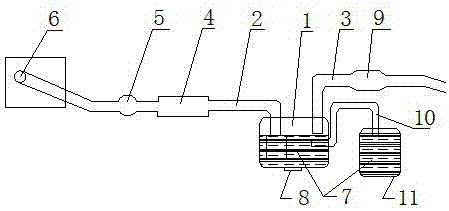
[0015] An automobile exhaust purifier, which consists of a cleaning and purification box 1, an air intake duct 2 and an exhaust duct 3 are housed in the cleaning and purification box, the air intake duct is connected to a muffler 4, and the muffler Connect the three-way catalytic converter 5 through the intake conduit, the three-way catalytic converter is connected to the engine exhaust discharge port 6 through the intake conduit, the exhaust gas purification solution 7 is housed in the described cleaning and purification box, and the described cleaning and purification Drainage valve 8 is equipped with at the bottom of the case. The automobile exhaust gas enters the bottom of the cleaning and purification box and then returns to the liquid surface, which is equivalent to taking a bath for the exhaust gas, filtering, adsorbing, neutralizing, melting, dissolving, precipitating, purifying, and filtering all the toxic and harmful components in the exhaust gas The cleaned gas is t...

Embodiment 2

[0017] As in the automobile exhaust purifier described in Embodiment 1, the exhaust duct includes a booster blower 9 . The exhaust gas produced by the automobile engine when it is working must pass through the three-way catalytic converter and the muffler. When the gas passes through the above devices, resistance will be generated, and this resistance will greatly reduce the engine power. The so-called power loss, the better the noise reduction effect, the greater the power consumption, and the loss is generally about 30%. In order to reduce this loss, a booster fan is designed. This device is installed at the end of the cleaning box of the three-way catalytic muffler. High power, reduce loss, and play a role in saving fuel.

Embodiment 3

[0019] As in the automobile exhaust purifier described in Embodiment 1 or 2, the cleaning and purification box further includes a communication conduit 10, and the communication conduit is connected to a backup tank 11, and the exhaust gas purification solution is contained in the backup tank.

[0020] When the exhaust gas passes through the cleaning and purification box, it will be absorbed, dissolved, precipitated, neutralized, and a certain amount of water will be evaporated. Therefore, an automatic water supply mechanism is installed on the cleaning and purification box. When the liquid level is lower than the requirement, this device will automatically supply liquid. , to ensure that the liquid level is at the required height. Automatic discharge device, when the liquid level is higher than the requirement, the switch on the device will automatically turn on the discharge, and dirt, impurities, sewage and dust particles will be generated in the box for a certain period of ...


PUM


Abstract

The invention provides a vehicle exhaust gas purifier. At present, a vehicle exhaust gas purifying device which is ideal in effect and capable of being widely applied is lacked. The vehicle exhaust gas purifier comprises a cleaning purifying tank (1) containing an exhaust gas purifying solution (7), a gas-intake duct (2) and a gas exhaust duct (3) are installed in the cleaning purifying tank, the gas-intake duct is connected with a silencer (4), the silencer is connected with a three-component catalyzing purifier (5) through the gas-intake duct, the three-component catalyzing purifier is connected with an engine exhaust gas exhausting port (6) through the gas-intake duct, and a blow-down valve (8) is installed at the bottom of the cleaning purifying tank. The vehicle exhaust gas purifier is used for purifying vehicle exhaust gas.

Description

[0001] The invention relates to an automobile tail gas purifier. Background technique [0002] At present, using a fuel engine as power has developed into one of the pillars of modern material civilization. According to incomplete statistics, the number of automobiles in the world has exceeded 600 million, and the annual emission of about 600 million tons of carbon monoxide, 100 million tons of carbon oxides and 50 million tons of nitrogen oxides, accounting for more than 60% of the total air pollution, is recognized The number one "killer" of the atmosphere. And the number of cars is increasing at a rate of more than 30 million every year. In addition to aircraft, ships and various mechanical equipment, the air pollution caused by exhaust gas has caused great harm to human health. At the same time, it will produce a greenhouse effect that will cause icebergs to melt, and sea levels will rise. Human living conditions are greatly challenged. If human beings do not control veh...

Claims


Application Information

Patent Timeline
Patent Type & Authority Applications(China)
IPC IPC(8): F01N13/00F01N3/04F01N3/08F01N13/08
CPCF01N13/009F01N3/04F01N3/08F01N13/00F01N13/082F01N2260/06
Inventor 陈道斌
Owner SUZHOU BOHAN ENVIRONMENTAL PROTECTION TECH
Why Eureka
Try Eureka