Kitchen garbage can
A technology for garbage cans and kitchens, applied in the kitchen field, can solve the problems of occupying a large space and taking out heavy garbage, and achieve the effects of reasonable discharge, improvement of multi-consideration cycle, and maintenance of cleanliness.
- Summary
- Abstract
- Description
- Claims
- Application Information
AI Technical Summary
Problems solved by technology
Method used
Image

Examples
Embodiment 1
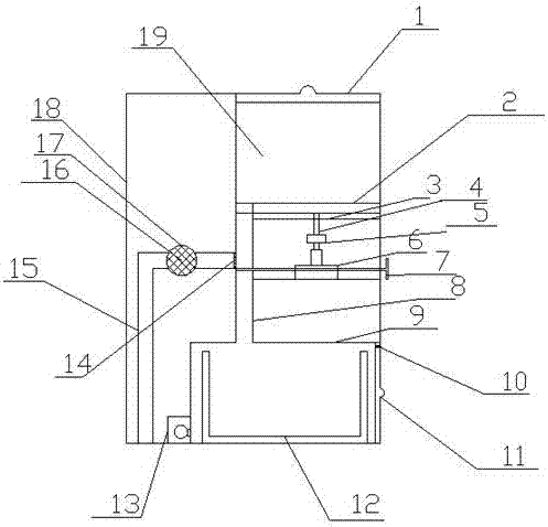
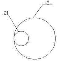
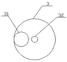
[0018] Such as figure 1 As shown in , a kitchen trash can includes: bucket end cover 1, turntable 2, chassis 3, connecting shaft 4, reducer 5, motor 6, barrier plate 7, round hole channel 8, storage room 9, belt stopper Air outlet 10, band end cap discharge port 11, storage tank 12, nitrogen storage tank 13, filter screen 14, water pipe 15, filter core 16, spherical filter tube 17, staving 18, cavity 19; 19 is arranged on the right side inside the barrel body 18, the barrel end cover 1 is arranged on the top of the cavity 19, the bottom of the cavity 19 is the chassis 3, the chassis 3 and the cavity 19 are fixedly connected, and the bottom of the cavity 19 is fixedly connected. A fixing hole 31 and a central through hole 32 are respectively provided, the fixing hole is arranged at the peripheral boundary of the chassis 3, the central through hole is arranged at the center of the chassis 3, a turntable 2 is arranged on the top of the cavity 19, and a turntable 2 is arranged on ...
Embodiment 2
[0027] The only difference from Example 1 is that the material of the turntable is polypropylene with sodium fluorosilicate and activated sericite powder added, sodium fluorosilicate and activated sericite in the polypropylene with sodium fluorosilicate and activated sericite powder It is made by kneading activated sericite powder and polypropylene at a mass ratio of 2:8:100.
[0028]The preparation method of the activated sericite powder is as follows: a certain amount of 800-mesh sericite powder is mixed with deionized water to prepare a sericite powder aqueous suspension with a mass concentration of 5.8%, adding 0.3% glycine of the sericite powder mass, adding Stir in a high-speed mixer at a speed of 2400r / min for 2 hours, then adjust the pH of the suspension to 3.8 with oxalic acid with a mass fraction of 0.28%, heat to 72°C, stir at a speed of 150r / min for 38min, and then add Suspension quality 0.12% ammonium persulfate, stir evenly, keep warm at 80°C for 15min, use 300W ...
Embodiment 3
[0032] The only difference from Example 1 is that the material of the turntable is polypropylene with sodium fluorosilicate and activated sericite powder added, sodium fluorosilicate and activated sericite in the polypropylene with sodium fluorosilicate and activated sericite powder It is made by kneading activated sericite powder and polypropylene at a mass ratio of 1:6:95.
[0033] The preparation method of the activated sericite powder is as follows: a certain amount of 800 mesh sericite powder is mixed with deionized water to prepare a sericite powder aqueous suspension with a mass concentration of 5.7%, adding 0.3% glycine of the sericite powder mass, adding Stir in a high-speed mixer at a speed of 2400r / min for 2 hours, then adjust the pH of the suspension to 3.8 with oxalic acid with a mass fraction of 0.28%, heat to 72°C, stir at a speed of 150r / min for 38min, and then add Suspension quality 0.12% ammonium persulfate, stir evenly, keep warm at 80°C for 15min, use 300W ...
PUM
 Abstract
Description
Claims
Application Information