
Conveyor system for electrothermal film element production line

A technology of conveying system and production line, applied in the field of conveying system, can solve problems such as polluting production lines, and achieve the effect of clean and tidy working environment, avoiding breakage and ensuring working environment.

Active Publication Date: 2019-06-04
CHENGDU YANGZHONG NEW ENERGY TECH
View PDF5 Cites 0 Cited by
  • Summary
  • Abstract
  • Description
  • Claims
  • Application Information

AI Technical Summary

Problems solved by technology

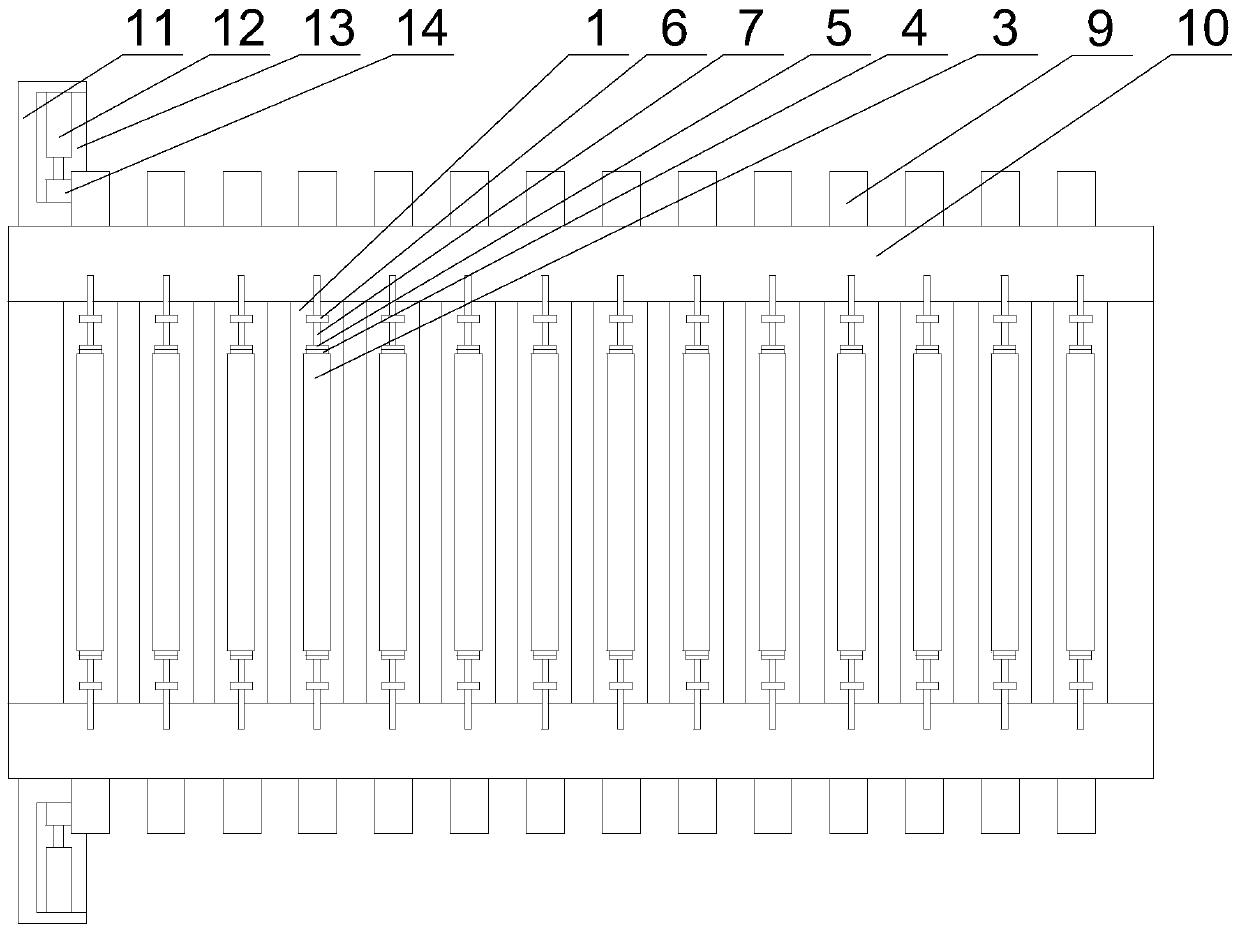
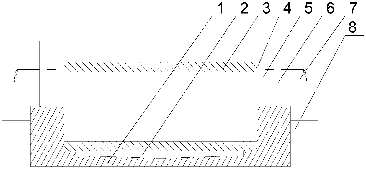
Aiming at the problem in the prior art that the transfer method used in all the processing steps of the glass tube will splash the attachments or residues on the glass tube, and then pollute the entire production line, the applicant based on the traditional rubber roller Above, a metal roller is used, and a rectangular groove for accommodating the glass tube is opened on the upper surface of the metal roller, and a plurality of rollers are rotated and set on the transmission chain, and the transmission chain drives the roller and the glass tube in the two processing processes. Movement between equipment, such as transmission between equipment corresponding to the coating process and sintering process, when the glass tube moves to the end of the transmission chain, the main gear and the transmission gear are in contact with each other through the lifting of the cylinder and the rotation of the motor , forcing the roller to turn over at a certain angle, and finally transferred by the pick-up equipment, that is, to realize the transfer of the glass tube between different process equipment; during the movement of the glass tube, the roller moves smoothly, and the adjacent two There will be no mutual interference between the glass tubes, and if the residue attached to the outer wall of the glass tube falls off, it will directly fall into the rectangular groove, which will not cause any pollution to the working environment of the production line

Method used


Image

  • Conveyor system for electrothermal film element production line
  • Conveyor system for electrothermal film element production line
  • Conveyor system for electrothermal film element production line

Examples


Embodiment 1

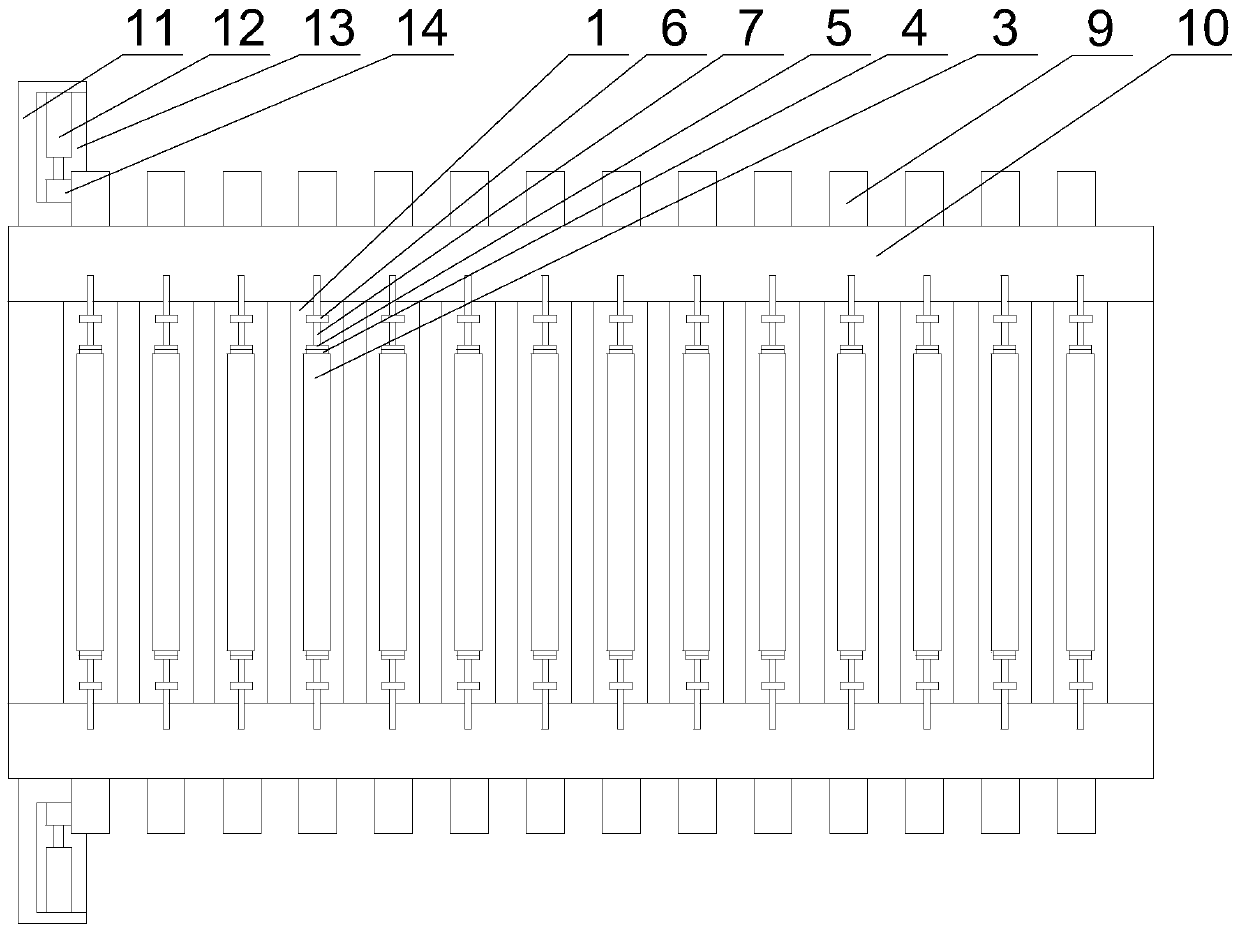
[0023] Such as Figure 1~2 As shown, this embodiment includes two transmission chains 10, and a plurality of rollers 1 perpendicular to the transmission chains are rotated between the two transmission chains, and the rotating shafts 8 at both ends of the rollers 1 move through the transmission The chain extends outwards, and a transmission gear 9 is installed on the rotating shaft 8, a rectangular groove for placing the glass tube 3 is opened on the upper surface of the roller 1, and a support 11 is provided on the side walls of the two transmission chains 10 , the vertically placed cylinder is fixed on the support 11, the output end of the cylinder is fixed with a base plate 13, the motor 12 is fixed on the base plate 13, and the output end of the motor 12 is equipped with a main gear that cooperates with the transmission gear 9 14, and in the initial state, the main gear 14 is located directly below the transmission gear 9, and the main gear 14 is not in contact with the tra...


PUM


Abstract

The invention discloses a conveying system for an electrothermal film element production line. The conveying system comprises two transmission chains; a plurality of rollers are rotationally arranged between the two transmission chains, rotating shafts at the two ends of each roller movably penetrate through the transmission chains and then extend outwards, and transmission gears are installed on the rotating shafts; a rectangular groove is formed in the upper surface of each roller; and supporting seats are arranged on the side walls of the two transmission chains, vertically-placed air cylinders are fixed to the supporting seats, bottom plates are fixed to the output ends of the air cylinders, motors are fixed on the bottom plates, and the output ends of the motors are provided with main gears matched with the transmission gears. In the moving process of glass tubes, the rollers move smoothly, mutual interference does not occur between every two adjacent glass tubes, and the residues attached to the outer walls of the glass tubes directly fall into the rectangular grooves after falling off and do not cause any pollution to the working environment of the production line.

Description

technical field [0001] The invention relates to the field of electrothermal film processing, in particular to a conveying system used in a production line of electrothermal film elements. Background technique [0002] The heating principle of the glass-coated heating tube: the glass-coated heating tube is a layer of doped oxide film formed on the surface of the insulating substrate by dipping, thermal spraying, evaporation and magnetron sputtering. Electrodes are placed on the layer to form a heating element. The heating tube preparation process includes glass tube cleaning, water glass coating, heating, spraying, grinding, electrical junction coating, sintering and testing. In all the processes of heating tube preparation, the glass tube needs to be transferred or conveyed. In the existing conveying mechanism, metal mesh conveyor belt or rubber conveying rubber roller is mostly used as the transfer part, and then in the processing technology, the glass tube During the tra...

Claims


Application Information

Patent Timeline
Patent Type & Authority Patents(China)
IPC IPC(8): B65G13/02B65G47/52
CPCB65G13/02B65G47/52
Inventor 李杨忠
Owner CHENGDU YANGZHONG NEW ENERGY TECH
Learn More