
Printing head screw rod device suitable for coarse aggregate concrete 3D printing

A print head and concrete technology, applied in the field of 3D printing, can solve the problems of large volume, difficult to control and use, and low fault tolerance of eccentric crankshaft pumps, and achieve the effects of reasonable structure, increased use range, and improved uniformity

Inactive Publication Date: 2017-09-15
CHINA STATE CONSTRUCTION ENGINEERING CORPORATION
View PDF4 Cites 5 Cited by
  • Summary
  • Abstract
  • Description
  • Claims
  • Application Information

AI Technical Summary

Problems solved by technology

[0004] Relying on the extrusion device of eccentric helix and double-wire helicoid, there are obvious limitations in the printing and extrusion of architectural 3D printing concrete:
[0005] (1) The general eccentric crankshaft pump can only convey and extrude the mortar material whose aggregate is sand, but cannot be applied when the aggregate is stone printing concrete material and steel fiber concrete material.
[0006] (2) The eccentric crankshaft pump relies on the tight wrapping of the crankshaft rotor and the double-wire screw rod sleeve, forming, conveying and extrusion pressure. During the conveying process of materials with sand, it is very easy to wear and tear, and there are a small amount of coarse foreign matter in the material , the print head will be stuck, and the fault tolerance rate is low
[0007] (3) The eccentric crankshaft pump that can realize the extrusion of small-sized fine stones is generally large in size, and the power of the power motor required is also large. After being made into a building 3D printing head, it is large and heavy, and it is difficult to control and use

Method used


Image

  • Printing head screw rod device suitable for coarse aggregate concrete 3D printing
  • Printing head screw rod device suitable for coarse aggregate concrete 3D printing
  • Printing head screw rod device suitable for coarse aggregate concrete 3D printing

Examples


Embodiment Construction

[0024] A printing head screw device suitable for 3D printing of coarse aggregate concrete of the present invention will be described in detail below in conjunction with specific embodiments and accompanying drawings:

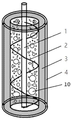
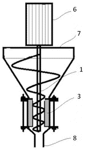
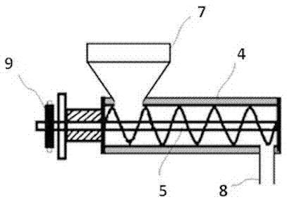
[0025] A structural schematic diagram of a print head screw device, such as figure 1 As shown, it includes a stator 4 and a rotor 5, the rotor 5 is arranged inside the stator 4, and it includes a straight rod 1 and a helical blade 2, and the helical blade 2 is evenly distributed on the straight rod 1; the stator 4 is a steel pipe and a An assembly of the flexible sleeve 3 , the flexible sleeve 3 is arranged between the helical blade 2 and the steel pipe, and the helical blade 2 on the rotor 5 is closely combined with the flexible sleeve 3 on the stator 4 .

[0026] When extruding printed concrete, there will be no extrusion pressure loss between the screw blade 2 and the flexible sleeve 3, which effectively ensures the uniformity of the extruded material.

[00...


PUM


Abstract

The invention discloses a printing head screw rod device suitable for coarse aggregate concrete 3D printing. The device comprises a stator and a rotor; the rotor is arranged in the stator, and comprises a straight rod and spiral blades; the spiral blades are uniformly distributed on the straight rod; the stator is a combined piece of a steel pipe and a flexible sleeve; the flexible sleeve is arranged between the spiral blades and the steel pipe; and the spiral blades on the rotor are tightly combined with the flexible sleeve on the stator. The printing head screw rod device can be applied to a concrete 3D printing head; a storage hopper on the printing head is arranged above the printing head screw rod device; and an extrusion port is positioned under the printing head screw rod device. The printing head screw rod device suitable for coarse aggregate concrete 3D printing is reasonable in structure; a wear-resistance rubber sleeve is arranged between the spiral blades of the rotor and a cover of the steel pipe; the blades are tightly combined with the rubber sleeve to guarantee consistent extrusion force, so that the discharge uniformity is improved; and the device can extrude concrete containing aggregates, and effectively widens the application range of a building 3D printer.

Description

technical field [0001] The invention relates to the technical field of 3D printing, in particular to a printing head screw device suitable for 3D printing of coarse aggregate concrete. Background technique [0002] For the extrusion print head of the construction 3D printing concrete material equipment, it should be able to extrude concrete with stones, and have stable flow, stable and controllable transmission power, self-priming function, low noise, high efficiency, long life and reliable operation specialty. At present, there are mainly two types of conveying pumps: plunger pump and screw pump, and these two pumps are mainly used for long-distance material transportation. Piston pumps are mainly used for concrete containing coarse aggregate, and screw pumps are mainly used for mortar transportation. [0003] However, since architectural 3D printing technology is a new technology that has emerged in recent years, there is no specific equipment for the extrusion head of t...

Claims


Application Information

Patent Timeline
IPC IPC(8): F04D3/02F04D7/00F04D29/02E04G21/00
Inventor 蔺喜强李景芳张涛霍亮李国友张楠廖娟王宝华戢文占
Owner CHINA STATE CONSTRUCTION ENGINEERING CORPORATION
Learn More