
Automatic collimation optical remote measurement system

An automatic collimation and telemetry system technology, applied in the field of optical telemetry, can solve the problems of small divergence angle, poor stability, short life, etc., and achieve the effect of increased detection distance, simple collimation structure, and long-distance detection

Inactive Publication Date: 2017-09-15
CHINA UNIV OF PETROLEUM (EAST CHINA)
View PDF0 Cites 3 Cited by
  • Summary
  • Abstract
  • Description
  • Claims
  • Application Information

AI Technical Summary

Problems solved by technology

Among the above methods, the collimation effect of the single lens method is poor, and the structure of the gradient index lens method, the liquid lens method, the reflection method and the diffraction method are too complicated. At present, only the combination lens method can guarantee the collimation effect of a certain accuracy, and at the same time avoid being too complicated Structure
[0004] Notification No. 202748542, a Chinese utility model patent titled "A Lens Collimation System for Semiconductor Laser Collimation" discloses a lens collimation system for semiconductor laser collimation, which uses two coaxial and The set meniscus lens can improve energy efficiency, reduce aberration, and has a small divergence angle. It is a kind of combined lens method, but at present, this method lacks environmental adaptability in actual use, especially in the face of different When the structure and distance reflect the target, it is necessary to manually adjust the position and spacing of the lens, which has poor stability and short life, and cannot conveniently adjust the spot at the target as needed

Method used


Image

  • Automatic collimation optical remote measurement system

Examples


Embodiment Construction

[0022] In the following, the present invention will be specifically described through exemplary embodiments. It should be understood, however, that elements, structures and characteristics of one embodiment may be beneficially incorporated in other embodiments without further recitation.

[0023] In the description of the present invention, it should be noted that the orientation or positional relationship indicated by the terms "inner", "outer", "upper", "lower", "front", "rear" etc. are based on the The positional relationship is only for the convenience of describing the present invention and simplifying the description, but does not indicate or imply that the referred device or element must have a specific orientation, be constructed and operated in a specific orientation, and thus should not be construed as limiting the present invention. The components may be independent, or multiple components may be integrated and assembled together.

[0024] The automatic collimating...


PUM


Abstract

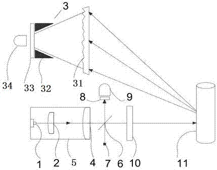
The invention belongs to the technical field of optical telemetry, and in particular relates to an optical telemetry system, which includes a collimator lens and an echo collection system located in front of the measuring laser. A beam splitter is set in front of the zoom lens in the coaxial direction, an aiming laser is set under the beam splitter, a reference gas chamber and a reference detector are set above the beam splitter, a part of the visible laser emitted by the aiming laser is transmitted through the beam splitter and enters the reference The gas chamber and the reference detector, part of the visible laser light emitted by the aiming laser is reflected by the beam splitter and coincides with the measurement laser of the measuring laser passing through the beam splitter, and the output window is located in front of the beam splitter.

Description

technical field [0001] The invention belongs to the technical field of optical telemetry, in particular to an optical telemetry system. Background technique [0002] Laser-based optical telemetry technology is generally used for ranging and positioning. Due to the path propagation, the echo signal carries rich information such as frequency, phase, and amplitude. After advanced weak signal processing technology, the information on the propagation path can be obtained, and then the purpose of remote sensing and telemetry can be realized. For example, for the absorption of a certain wavelength band by the medium components in the path, the concentration of the medium can be reversed by modulating the absorption spectrum technology, so as to realize remote measurement. For another example, a certain vibration source on the path passively modulates the light wave carrier frequency signal, and the information of the vibration source can be recovered through demodulation, so as ...

Claims


Application Information

Patent Timeline
Patent Type & Authority Applications(China)
IPC IPC(8): G01S17/02G01S7/481
CPCG01S17/02G01S7/481
Inventor 季文海宋迪李国林
Owner CHINA UNIV OF PETROLEUM (EAST CHINA)
Learn More