Permanent magnet motor rotor sheath with heat bridges and wind stirring plate structures, and permanent magnet motor

A rotor sheath and permanent magnet motor technology, applied in the direction of magnetic circuit rotating parts, magnetic circuit shape/style/structure, electric components, etc., can solve the problem of affecting the efficiency and safe operation of the motor, reducing the cooling effect of the motor, and the air gap of the motor Small space and other problems to achieve the effect of preventing thermal demagnetization, lowering the temperature, and accelerating the axial ventilation of the air gap

Active Publication Date: 2017-09-15
BEIJING JIAOTONG UNIV
View PDF3 Cites 1 Cited by
  • Summary
  • Abstract
  • Description
  • Claims
  • Application Information

AI Technical Summary

Problems solved by technology

When the motor is running for a long time, if the heat cannot be dissipated in time and quickly, it will cause the temperature of the permanent magnet to be too high, which will affect its electromagnetic performance. In severe cases, it will cause demagnetization of the permanent magnet, which will affect the efficiency and safe operation of the motor.
When the cooling gas of the traditional cooling system enters the air gap section of the motor, the cooling effect of the motor is reduced due to the small air gap space of the motor and the limited flow rate of the cooling gas.

Method used


Image

  • Permanent magnet motor rotor sheath with heat bridges and wind stirring plate structures, and permanent magnet motor
  • Permanent magnet motor rotor sheath with heat bridges and wind stirring plate structures, and permanent magnet motor
  • Permanent magnet motor rotor sheath with heat bridges and wind stirring plate structures, and permanent magnet motor

Examples


Embodiment Construction

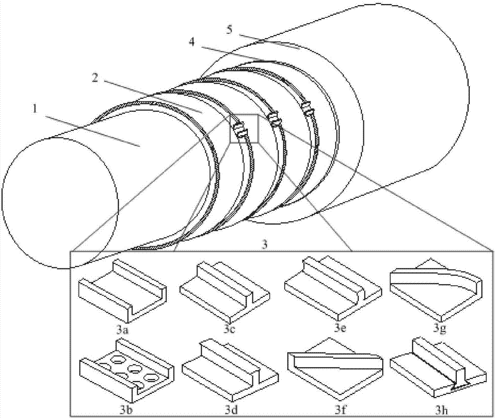
[0036] figure 1 It is a schematic diagram of a motor with a rotor sheath with a thermal bridge and a wind stirring plate structure in the present invention. The motor is mainly composed of a rotor 1, a segmented rotor sheath 2, a thermal bridge 3 with a wind stirring plate structure, and a stator 5. , there is an air gap 4 between the rotor 1 and the stator 5 . Compared with the existing motor structure, the above-mentioned structure has a plurality of heat bridges and wind stirring plate structures evenly arranged between the segmented rotor sheaths along the circumferential direction of the rotor, such as Figure 2-Figure 9 Shown is a schematic diagram of the thermal bridge of various wind stirring plate structures, which are suitable for different operating conditions of the motor.

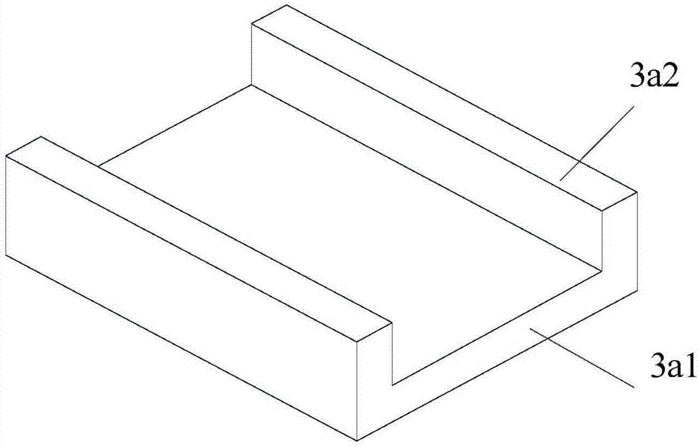
[0037] by figure 2 The structure of the railing type wind stirring board thermal bridge 3a is taken as an example, wherein the railing type wind stirring board thermal bridge body 3a1 is use...


PUM


Abstract

The invention provides a permanent magnet motor rotor sheath with heat bridges and wind stirring plate structures. The structure of the permanent magnet motor rotor sheath with heat bridges and wind stirring plate structures is that heat bridge structures are uniformly arranged between sectional type sheathes of a permanent magnet motor in the circumferential direction of a rotor; wind stirring plates in a plurality of structures are arranged on the heat bridges, thus being suitable for different operating conditions of the motor; the wind stirring plates and the heat bridges are integrated into one body, and the wind stirring plates go deep into half of the motor air gap; when the wind stirring plates and the heat bridges are identical in the property of materials, the overall body can be formed through casting and is welded with the sheathes; when the wind stirring plates employ the heat conduction non-magnetic-conductive conductive materials, the wind stirring plates are connected with the heat bridges in a plugging type structure, and the combination clearance is encapsulated and conducts heat by means of epoxy resin; and when the rotor rotates, the wind stirring plates stir the air in the motor air gap to flow in the circumferential and radial directions, and at the same time stir the air in the air gap to bi-directionally or unidirectionally flow in the axial direction to accelerate heat radiation of the stator, the rotor and the permanent magnet. The permanent magnet motor rotor sheath with heat bridges and wind stirring plate structures is novel and simple in design; the higher the rotation speed of the motor is, the better the cooling effect is; and by means of coordination with other cooling systems, the usage effect becomes better.

Description

technical field [0001] The invention relates to a motor, in particular to a rotor sheath structure of a permanent magnet motor. The sheath structure is provided with a thermal bridge and a wind stirring plate structure. Background technique [0002] When the motor is actually running, the harmonic magnetic field will generate large eddy currents on the surface of the rotor permanent magnet and the rotor sheath, and the heat loss generated by the eddy current will cause the temperature of the permanent magnet to rise. When the motor is running for a long time, if the heat cannot be dissipated in time and quickly, the temperature of the permanent magnet will be too high, which will affect its electromagnetic performance. In severe cases, the permanent magnet will be demagnetized, which will affect the efficiency and safe operation of the motor. When the cooling gas of the traditional cooling system enters the air gap section of the motor, due to the small air gap space of the ...

Claims


Application Information

Patent Timeline
Patent Type & Authority Applications(China)
IPC IPC(8): H02K1/27H02K11/01H02K9/06
CPCH02K1/27H02K9/06H02K11/01
Inventor 李伟力刘文茂李琳李栋张晓晨曹君慈高晗璎沈稼丰
Owner BEIJING JIAOTONG UNIV
Why Eureka
Try Eureka