
Machining method of long-and-thin walled cylindrical component

A processing method and technology for thin-walled cylinders, which are applied in the field of cylindrical parts processing, can solve the problems of non-standard interference fit of long thin-walled cylindrical parts, difficult to meet design requirements, unqualified operation tests, etc., and achieve remarkable processing effects. The effect of satisfying operability and avoiding manufacturing errors

Inactive Publication Date: 2017-09-19
SHENYANG TURBO MASCH CORP
View PDF6 Cites 20 Cited by
  • Summary
  • Abstract
  • Description
  • Claims
  • Application Information

AI Technical Summary

Problems solved by technology

In the finishing process of this processing method, each part of the long and thin-walled cylindrical part is often processed to the amount at one time, and the stress generated during processing cannot be released. When clamping the chuck at one end and the outer diameter of the other end, due to the cylindrical The wall thickness of the part is small, and it is easy to deform during the clamping process, and the shape and position tolerances such as coaxiality during the finishing process are often difficult to meet the design requirements
In this way, the interference fit of the long and thin-walled cylindrical parts is not up to standard during the final assembly procedure, resulting in failure of the operation test of the rotor and even the complete machine in the factory.

Method used


Image

  • Machining method of long-and-thin walled cylindrical component
  • Machining method of long-and-thin walled cylindrical component
  • Machining method of long-and-thin walled cylindrical component

Examples


Embodiment Construction

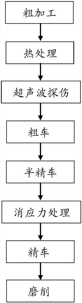
[0022] see figure 1 , the invention provides a kind of processing method of long thin-walled cylindrical part, comprises the steps:

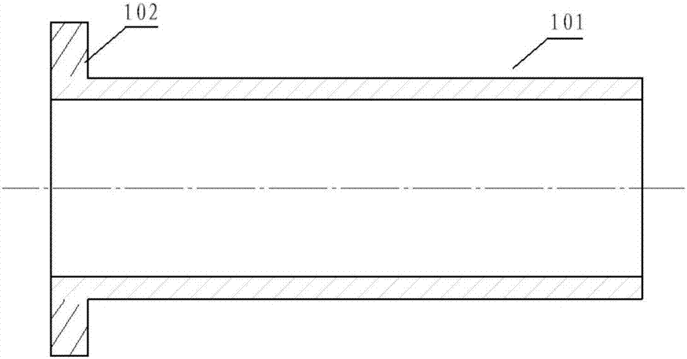
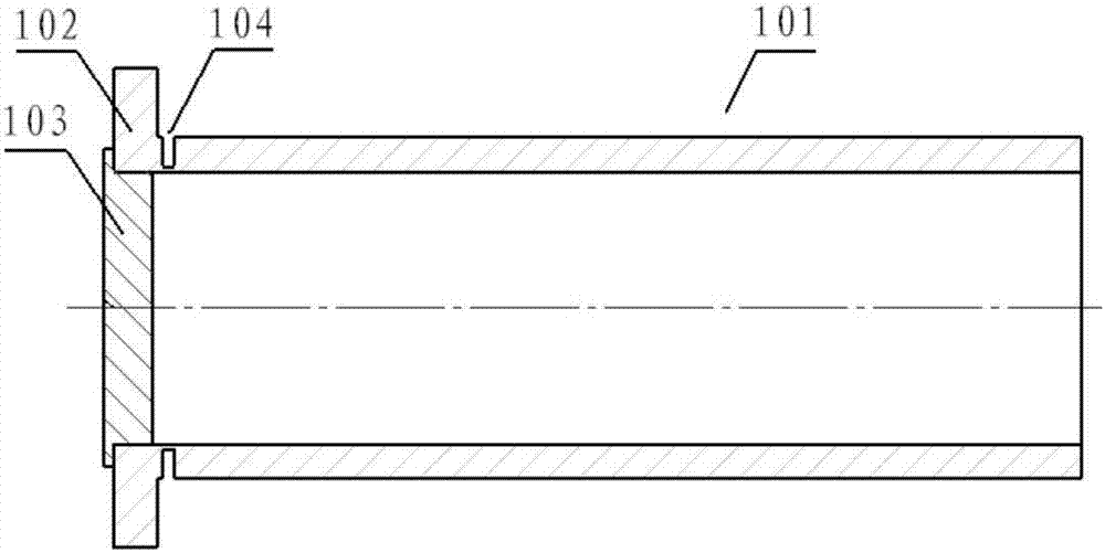
[0023] Rough machining: use cylindrical forged steel as the raw material 101 for rough machining, and use the three-jaw chuck of a horizontal lathe to clamp one end of the blank 101 according to the heat treatment rough machining pattern, as a specific embodiment of the present invention , the clamping is the left end of the blank 101, and one end of the blank 101 is the right end. The outer circle of the rough-turned blank 101 retains the part of the clamping end that has not been roughly machined, so that a chuck 102 is formed at the clamping position, and the inner hole of the rough-cut blank 101 and the right end surface of the blank 101 are rough-turned from the right end of the blank 101, and fully The machining allowance of the outer circle, inner hole and right end face is reserved, and the workpiece obtained after rough machining is as...


PUM


Abstract

The invention provides a machining method of a long-and-thin walled cylindrical component, and belongs to the technical field of machining of cylindrical components. The method comprises the following steps: carrying out rough machining to obtain a rough machining workpiece with a chuck; carrying out quenching and tempering treatment on the workpiece subjected to rough machining; carrying out ultrasonic flaw detection on the workpiece; carrying out rough turning and half finished turning of the workpiece; carrying out stress elimination treatment on the workpiece; caryring out finished turning of the workpiece; placing a circular disc shaped support part in an inner hole of a chuck end; clamping the chuck; carrying out finished turning of an outer circle and the inner hole; radially cutting a groove on the outer circle of the workpiece close to the chuck part; then carrying out finished turning of the inner hole and the end surface of the other end to a designed size; finally, cutting off the end provided with the chuck; milling and cutting off the end surface of the workpiece of the chuck end to the length of the workpiece to meet the design requirement. According to the machining method of the long-and-thin walled cylindrical component, the deformation of the workpiece during clamping can be avoided, the machining stress of the workpiece can be effectively released, and the situation that coaxial degree of the workpiece meets the design requirement can be guaranteed.

Description

technical field [0001] The invention relates to the technical field of processing cylindrical parts, in particular to a processing method for long and thin-walled cylindrical parts. Background technique [0002] The centrifugal compressor rotor is composed of multiple parts, some of which are long and thin-walled cylindrical structures, and their specifications are usually 150mm-200mm in outer diameter, 10mm-15mm in wall thickness, and 300mm-400mm in length. Common grades of materials are 12Cr13, 45#, 25Cr2Ni3Mo forgings. [0003] The current method of processing such long and thin-walled cylindrical parts usually adopts the processing process of rough machining→rough turning→finish turning. In the finishing process of this processing method, each part of the long and thin-walled cylindrical part is often processed to the amount at one time, and the stress generated during processing cannot be released. When clamping the chuck at one end and the outer diameter of the other ...

Claims


Application Information

Patent Timeline
IPC IPC(8): B23P15/00
CPCB23P15/00
Inventor 刘姝鑫白俊峰宋健
Owner SHENYANG TURBO MASCH CORP
Features
  • Generate Ideas
  • Intellectual Property
  • Life Sciences
  • Materials
  • Tech Scout
  • Unparalleled Data Quality
  • Higher Quality Content
  • 60% Fewer Hallucinations
Learn More