Unmanned aerial vehicle

A technology for unmanned aerial vehicles and fuselages, which is applied in the direction of unmanned aircraft, rotorcraft, motor vehicles, etc., and can solve the problem that the landing gear does not have a shock-absorbing and buffering effect, the gimbal cannot be quickly disassembled, and the battery box is not limited. Problems such as bit structure, to achieve the effect of easy promotion, simple and reasonable structure, quick disassembly and assembly

Active Publication Date: 2017-09-19
WENZHOU TONG XIANG INTELLIGENT TECH CO LTD
View PDF8 Cites 7 Cited by
  • Summary
  • Abstract
  • Description
  • Claims
  • Application Information

AI Technical Summary

Problems solved by technology

[0007] In order to overcome the deficiencies in the background technology, the present invention provides an unmanned aerial vehicle, which mainly solves the problems that the existing unmanned aerial vehicles cannot be quickly disassembled and assembled, the battery box does not have a limiting structure, and the landing gear does not have a shock absorbing and buffering effect. The structure of the UAV is simple and reasonable. Through the mounting slot of the hanging plate and the hanging plate of the gimbal, the opening or locking state is controlled by the rotation of the wrench, so as to achieve the effect of quick disassembly and assembly of the gimbal. The matching locking hook and locking groove are set on the lower partition to prevent the effect of the battery box moving when the drone vibrates. At the same time, the connecting arm, lifting feet and telescopic connecting rod are hinged to each other. The telescopic connecting rod includes a connecting rod shaft And the bushing, the connecting rod shaft and the bushing are connected through the compression spring III, so that the landing gear can achieve the shock absorption and buffering effect when the UAV lands, greatly improving the overall performance of the UAV, practical and convenient, high reliability, and easy to operate. Stable, long service life, easy to promote

Method used


Image

  • Unmanned aerial vehicle
  • Unmanned aerial vehicle
  • Unmanned aerial vehicle

Examples


Embodiment Construction

[0032] Embodiments of the present invention will be further described below in conjunction with accompanying drawings:

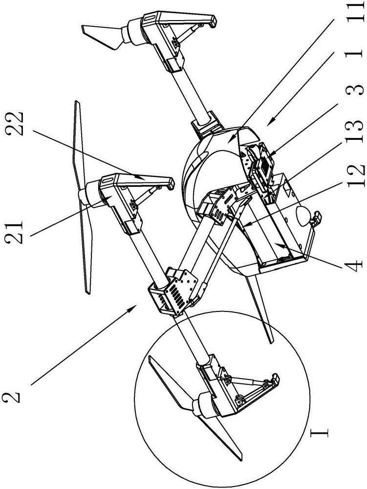
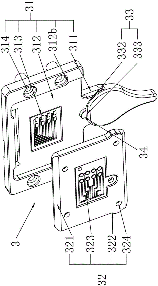
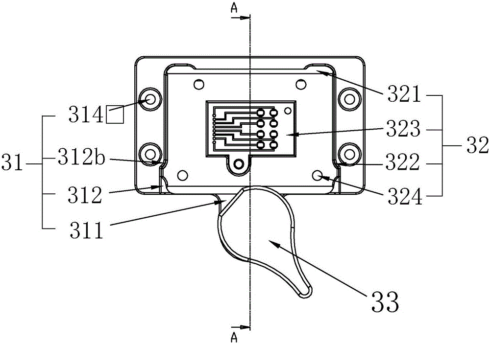
[0033] Such as Figures 1 to 12Shown, a kind of unmanned aerial vehicle, it comprises unmanned aerial vehicle body 1 and unmanned aerial vehicle frame 2 that are connected to each other, and unmanned aerial vehicle frame 2 is provided with driving device 21 and landing gear 22, and unmanned aerial vehicle machine The body 1 includes a fuselage shell 11 and a driving part, a transmission part and a mounting part arranged in the fuselage shell 11. The mounting part includes an upper partition, a middle partition 12 and a lower partition 13 arranged in parallel to each other. The lower side of the lower partition 13 is provided with a quick-release pan-tilt assembly 3 connected thereto. The quick-release pan-tilt assembly 3 includes a pan-tilt mother part 31, a pan-tilt hanging plate 32 and a wrench 33. It is fixedly connected with the lower partition 13. One ...


PUM


Abstract

The invention relates to an unmanned aerial vehicle. The unmanned aerial vehicle comprises an unmanned aerial vehicle fuselage and an unmanned aerial vehicle rack which are mutually connected. A driving device and an undercarriage are arranged on the unmanned aerial vehicle rack, the unmanned aerial vehicle fuselage comprises a fuselage outer shell, a driving part, a transmission part and a mounting part, wherein the driving part, the transmission part and the mounting part are arranged in the fuselage outer shell. The mounting part comprises an upper baffle, a middle baffle and a lower baffle which are mutually parallelly arranged. A quick-release pan-tilt assembly mutually connected with the lower baffle is arranged on the lower side of the lower baffle, the quick-release pan-tilt assembly comprises a pan-tilt parent part, a pan-tilt hanging panel and a spanner, and a protruding structure is arranged at one end of the pan-tilt parent part; and the protruding structure and the spanner are mutually connected in a hinged mode through arrangement of a spanner mounting position, and the pan-tilt parent part and the pan-tilt hanging panel are mutually clamped through arrangement of a hanging-panel mounting groove. According to the unmanned aerial vehicle, the structure is simple and reasonable, rapid disassembly and assembly of a pan-tilt are achieved, and a battery box is prevented from moving; the undercarriage has damping and buffering effects in the landing process, practicability and convenience are achieved, and the reliability is high; and operation is stable, the service life is long, and popularization is easy.

Description

technical field [0001] The invention relates to the technical field of miniature unmanned aerial vehicles, in particular to an unmanned aerial vehicle. Background technique [0002] At present, micro-UAVs have a broad background in both military and civilian industries. They can be used for near-ground monitoring, reconnaissance and other tasks, and can also be used for short-term indoor and outdoor aerial photography projects. Existing drones have the following problems: [0003] 1. The connection between the drone and the gimbal is often complicated, and users cannot quickly install and disassemble the gimbal, which affects the overall performance of the drone. [0004] 2. The battery box on the drone is often not equipped with a limit structure. The drone will be affected by external factors during use, and the body of the drone will vibrate, causing the battery box to move and causing power supply interruption or instability. And so on, affect the normal use of UAV. ...

Claims


Application Information

Patent Timeline
Patent Type & Authority Applications(China)
IPC IPC(8): B64C27/08B64C25/62B64D47/00B64D47/08
CPCB64C25/62B64C27/08B64D47/00B64D47/08B64U10/10B64U2101/30
Inventor 郑伯省
Owner WENZHOU TONG XIANG INTELLIGENT TECH CO LTD
Why Eureka
Try Eureka