Real-time intelligent logging system of coiled tubing with optical cable

A tubing and optical cable technology, applied in the field of coiled tubing real-time intelligent logging system, can solve problems such as affecting the judgment of staff, slow transmission speed, unsatisfactory cable transmission effect, etc., and achieve fast signal transmission rate and high accuracy. Effect

Active Publication Date: 2017-09-19
广东迅维科技发展有限公司
View PDF10 Cites 9 Cited by
  • Summary
  • Abstract
  • Description
  • Claims
  • Application Information

AI Technical Summary

Problems solved by technology

The transmission technology of the measurement signal generally uses the downhole data encoder to convert the data into a sound wave signal, uses the sound wave to transmit the wireless data, and then uses the wellhead sensor to monitor the sound wave signal, decodes and restores it to the original construction data, and finally transmits it to the data processing system for data processing. However, the acoustic signal will be attenuated during the transmission process, and the transmission speed is relatively slow. When the logging instrument is located in a deep position, it will take a certain amount of time to transmit to the well until the staff observes It has gone through a long time, so there are certain errors and hysteresis, which will affect the judgment of the staff; in the prior art, cables are also used for data transmission, but the transmission effect of cables is not satisfactory.

Method used


Image

  • Real-time intelligent logging system of coiled tubing with optical cable
  • Real-time intelligent logging system of coiled tubing with optical cable
  • Real-time intelligent logging system of coiled tubing with optical cable

Examples


Embodiment Construction

[0037] The technical solutions in the embodiments of the present invention will be clearly and completely described below in conjunction with the drawings in the present invention. Apparently, the described embodiments are only some of the embodiments of the present invention, not all of them. Based on the embodiments of the present invention, all other embodiments obtained by persons of ordinary skill in the art without making creative efforts belong to the protection scope of the present invention.

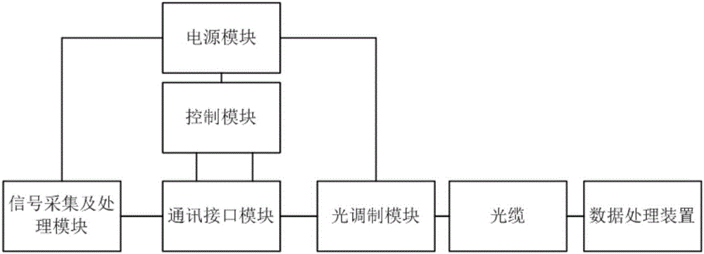
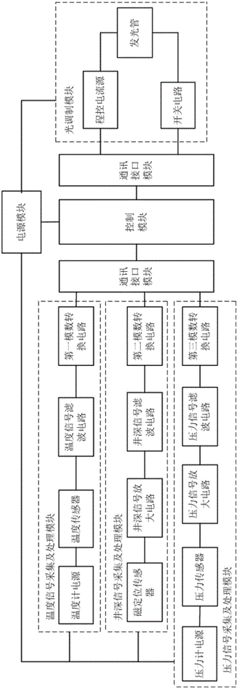
[0038]A coiled tubing real-time intelligent logging system with an optical cable according to the first embodiment of the present invention includes a data processing device located on the ground, a measuring device located in the oil well, and a coiled tubing optical cable assembly located between the data processing device and the measuring device. The function of the measuring device is to measure various parameters in the oil well, such as temperature parameters, pressure par...


PUM


Abstract

The invention relates to the technical field of coiled tubing logging, in particular to a real-time intelligent logging system of coiled tubing with an optical cable. The real-time intelligent logging system comprises a data processing device located on the ground, a measuring device located in an oil well and a coiled tubing optical cable assembly located between the data processing device and the measuring device; the measuring device comprises a logging instrument carrier and a circuit assembly located inside the logging instrument carrier; and the circuit assembly comprises a power supply module, a control module, a communication interface module, a signal acquisition and processing module and a light modulation module. The light modulation module converts a signal measured by the measuring device into a light signal, through the optical cable or an optical fiber, the light signal is transmitted to the data processing device on the ground to be calculated and analyzed, due to the fact that the signal transmission speed of the optical cable or the optical fiber is high, and accuracy is high, real-time transmission of downhole data is achieved, and workers on the ground can know an environment in the oil well in real time and make work deployment timely.

Description

technical field [0001] The invention relates to the field of coiled tubing logging technology, in particular to a coiled tubing real-time intelligent logging system with an optical cable. Background technique [0002] In the coiled tubing logging process, the real-time acquisition and transmission technology of bottom hole data is an important means to improve the efficiency of coiled tubing logging. The coiled tubing logging process uses downhole logging instruments to measure various parameters in the oil well, such as temperature and pressure. Parameters are the main downhole parameters. After the measurement, the data is transmitted to the uphole data processing system by a certain method. After sorting, analyzing and comparing the data, it can be converted into a directly observable parameter chart, which is convenient for the downhole environment. Make a judgment, and then draw a work plan for the next step. [0003] In the existing technology, different types of sens...

Claims


Application Information

Patent Timeline
Patent Type & Authority Applications(China)
IPC IPC(8): E21B47/00E21B47/06E21B47/07E21B47/12G01D21/02G05D25/02
CPCG05D25/02E21B47/00E21B47/06E21B47/12G01D21/02E21B47/07
Inventor 杨冬许洪波
Owner 广东迅维科技发展有限公司
Why Eureka
Try Eureka